
Semi-automatic wire binding device for bunching test

A test, semi-automatic technology, applied in the direction of cable installation, electrical components, cable installation devices, etc., can solve time-consuming and labor-intensive problems

Pending Publication Date: 2022-05-31
JIANGSU ZHONGLI GRP CO LTD +1
View PDF0 Cites 0 Cited by
  • Summary
  • Abstract
  • Description
  • Claims
  • Application Information

AI Technical Summary

Problems solved by technology

Bind the cables to the ladder with iron wires. The traditional method uses tools such as pliers and scissors. It is necessary to switch tools such as pliers and scissors frequently, which is time-consuming and laborious.

Method used


Image

  • Semi-automatic wire binding device for bunching test

Examples


Embodiment Construction

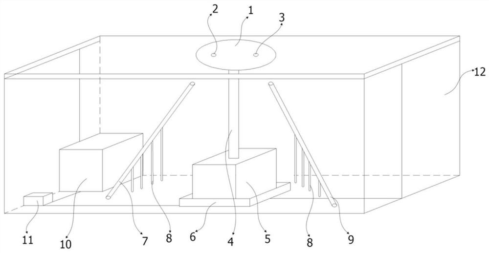
[0013] like figure 1 As shown in the figure, the semi-automatic wire binding device for bundling test includes a casing 12, and a transmission rod 4, a rotary power mechanism 5, a wire inlet guide 7, and a wire outlet guide 8 are installed in the casing 12. A transmission wheel 1 is installed, and the transmission wheel 1 is installed on the rotary power mechanism 5 through the transmission rod 4 , and the rotary power mechanism 5 has a shock-absorbing pad 6 under the rotary power mechanism 5 . Specifically, the rotary power mechanism 5 is a motor. In order to facilitate binding, the transmission wheel 1 is located outside the casing 12 .

[0014] A battery box 10 is also installed in the casing 12 , and the battery box 10 is connected to the rotary power mechanism 5 through a switch 11 to realize switch control.

[0015] The transmission wheel 1 has a wire inlet hole 2 and a wire outlet hole 3. Below the transmission wheel 1, the wire inlet hole 2 is provided with a wire in...


PUM


Abstract

The invention discloses a semi-automatic wire binding device for a bunching test, which comprises a shell, a transmission rod, a rotary power mechanism, a wire inlet guide pipe and a wire outlet guide pipe are arranged in the shell, a transmission wheel is arranged on the transmission rod, the transmission wheel is arranged on the rotary power mechanism through the transmission rod, and the transmission wheel is provided with a wire inlet hole and a wire outlet hole; below the transmission wheel, a wire inlet guide pipe is arranged at the edge of the wire inlet hole, and a wire outlet guide pipe is arranged at the edge of the wire outlet hole; traditional manual wire binding is replaced by semi-automatic wire binding, frequent tool switching is not needed, iron wire winding is firmer than traditional means, and rapid and efficient cable binding is achieved.

Description

technical field [0001] The invention relates to a semi-automatic wire binding device for bundling test, which is used for bundling cables. Background technique [0002] Before the cable bundle burning test, the cables need to be bundled with iron wires on the ladder (or other frame). The bundled burning test requires a large number of cables, so there will be more connection parts with the ladder, and the binding is tight. There are certain requirements. The cable is tied to the ladder with iron wire. The traditional method uses tools such as vise and scissors, which requires frequent switching of vise, scissors and other tools, which is time-consuming and labor-intensive. SUMMARY OF THE INVENTION [0003] The technical problem to be solved by the present invention is to provide a semi-automatic wire binding device for bundling test, which can quickly and efficiently bind cables. [0004] In order to solve the above-mentioned technical problems, the semi-automatic wire b...

Claims


Application Information

Patent Timeline
Patent Type & Authority Applications(China)
IPC IPC(8): H02G1/00
CPCH02G1/00
Inventor 刘圆松张锐卢柏会闫俊桥王鑫虹屈魁琳魏辰冰刘戈刘焱鑫
Owner JIANGSU ZHONGLI GRP CO LTD
Learn More