Adjustable reactance current limiting reactor

A technology of current-limiting reactors and reactors, applied in the field of electric power, can solve problems such as single function, single applicable environment, and inconvenient use

Pending Publication Date: 2022-05-31
戴永春
View PDF0 Cites 0 Cited by
  • Summary
  • Abstract
  • Description
  • Claims
  • Application Information

AI Technical Summary

Problems solved by technology

[0004] The technical problem solved by the present invention is to overcome the shortcomings of the prior art such as single function, inconvenient use, and single applicable environment, and provide a current-limiting reactor with adjustable reactance

Method used


Image

  • Adjustable reactance current limiting reactor
  • Adjustable reactance current limiting reactor
  • Adjustable reactance current limiting reactor

Examples


Embodiment Construction

[0024] The following will clearly and completely describe the technical solutions in the embodiments of the present invention with reference to the accompanying drawings in the embodiments of the present invention. Obviously, the described embodiments are only some, not all, embodiments of the present invention. Based on the embodiments of the present invention, all other embodiments obtained by persons of ordinary skill in the art without making creative efforts belong to the protection scope of the present invention.

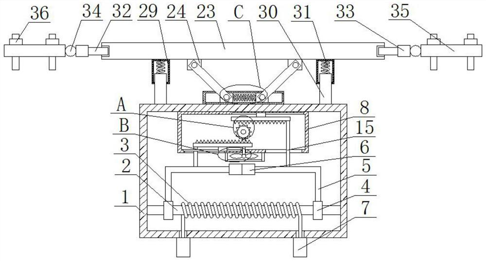
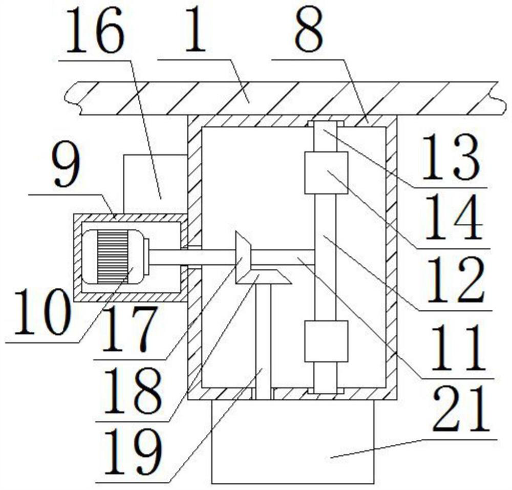
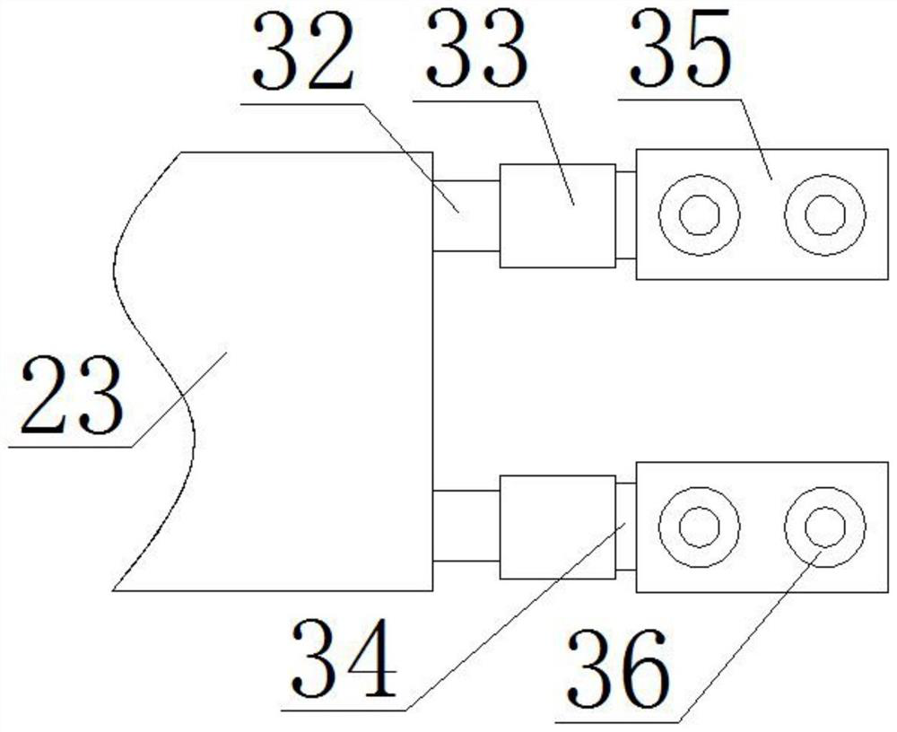
[0025] see Figure 1-6 , the present invention provides a technical solution: a current-limiting reactor with adjustable reactance, including a reactor housing 1, the inner cavity of the reactor housing 1 is fixedly connected with a conductive rod 2 near the bottom, and the conductive rod 2 A coil 3 is sheathed at the center of the outer edge, and the bottom of the reactor housing 1 is fixedly connected with binding posts 7 close to the left and right sides. ...


PUM


Abstract

The adjustable reactance current limiting reactor comprises a reactor shell, a conducting rod is fixedly connected to the position, close to the bottom, of an inner cavity of the reactor shell, a coil is arranged at the center of the edge of the outer side of the conducting rod in a sleeving mode, and binding posts are fixedly connected to the positions, close to the left side and the right side, of the bottom of the reactor shell. The bottom ends of the coils penetrate through the bottom of an inner cavity of the reactor shell and are fixedly connected with the adjacent binding posts, conducting rings are arranged at the positions, close to the left end and the right end, of the edge of the outer side of a conducting rod in a sleeving mode, and through mutual cooperation of mechanisms such as an L-shaped rod, a contact, a rotating rod, a transmission gear, a sliding block, a rack, an insulation connecting rod and a control box, the electric reactor can be stably connected. Current limiting and circuit protection effects can be realized, and buffering and noise reduction effects on the reactor can be realized through mutual cooperation of mechanisms such as a fixed block, a connecting rod, a frame body, a movable block, a first spring, a limiting box, a movable rod and a second spring.

Description

technical field [0001] The invention relates to the field of electric power technology, in particular to an adjustable reactance current-limiting reactor. Background technique [0002] With the rapid development of the power system, the capacity of single machine, the capacity of power plants, the capacity of substations, the increase of load and load density in cities and industrial centers, and the interconnection between power systems have led to the continuous increase of the short-circuit current in the power system. At present, Excessive short-circuit current or even exceeding the standard has become an important factor restricting the development of the power grid. Replacing switches is one of the means to solve the problem of short-circuit current exceeding the standard. However, substations with excessive short-circuit current are generally hub substations. The equipment and grounding grid also need to be replaced. Although the replacement of the switch has no effec...

Claims


Application Information

Patent Timeline
IPC IPC(8): H01F27/06H01F27/28H01F27/33H01F27/02
CPCH01F27/06H01F27/2876H01F27/33H01F27/02Y02E40/30
Inventor 戴永春
Owner 戴永春
Why Eureka
Try Eureka