Forming preparation method of fiber composite material shell of solid rocket engine
A fiber composite material, solid rocket technology, applied in rocket engine devices, machines/engines, mechanical equipment, etc., can solve problems such as low yield and unstable product performance, achieve controllable mechanical properties, reduce process costs, and improve consistency. sexual effect
Pending Publication Date: 2022-05-31
NANJING UNIV OF TECH
View PDF4 Cites 3 Cited by
- Summary
- Abstract
- Description
- Claims
- Application Information
AI Technical Summary
Problems solved by technology
[0009] In order to solve the problems of low yield and unstable product performance in the traditional process of composite material shells in the prior art, the present invention proposes a molding preparation method for solid rocket motor carbon fiber composite shells
Method used
View moreImage
Smart ImageViewing Examples

Examples
Embodiment 1
[0073] The surface of the processed pultruded 0 degree fiber layer is roughened and coated with an adhesive, and then assembled on the two sides.
[0074] Afterwards, on the basis of the "assembly" of the previous step, the hoop direction (90 degrees) of the outer layer carbon fiber (model T1000) is carried out
Login to View More PUM
 Abstract
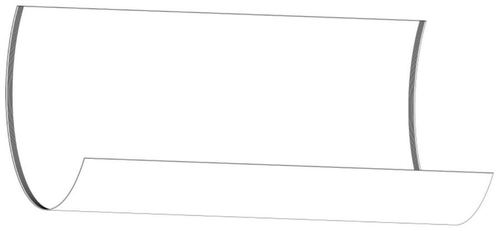
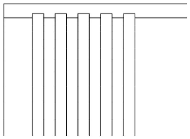
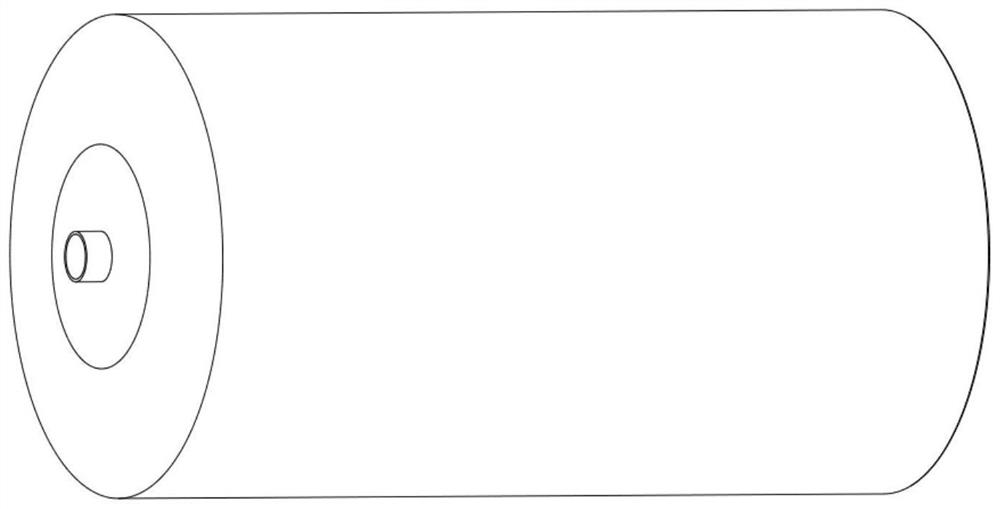
The invention relates to a forming preparation method of a fiber composite material shell of a solid rocket engine. Comprising the following steps: preparing an inflatable rubber core mold; preparing a lining layer and a heat insulating layer on the outer layer of the rubber core mold; a plurality of 0-degree fiber layers of which the sections are arc sections are arranged in two pultrusion ends; preparing an integrated metal piece, wherein the integrated metal piece comprises pre-tightening force teeth matched with the tooth grooves of the 0-degree fiber layer, a connecting flange, a butt joint skirt and an end socket; the two integrated metal pieces and the multiple 0-degree fiber layers with the sections being arc sections are assembled, and a combination is obtained; a fiber layer is wound around the periphery of the combined body in the circumferential direction, and the shell is obtained after curing forming. The 0-degree fiber layer and the 90-degree fiber layer are arranged, and through tooth connection of the integrated metal piece and the inflatable rubber core mold, the rigidity and bearing requirements of the solid rocket engine shell are met, rapid and repeated use of the core mold is achieved, and low cost and high performance of composite shell preparation are achieved.
Description
A kind of molding preparation method of solid rocket motor fiber composite material shell technical field The invention belongs to the motor housing field, be specifically related to a kind of solid rocket motor fiber composite material housing. Forming preparation method. Background technique [0002] The solid rocket motor composite shell mainly includes front and rear butt skirts, a head, a wound fiber layer, a thermal insulation layer and lining. In the prior art, the connecting flange structures at the front and rear ends are generally installed on the thermal insulation layer, and outside the connecting flange structure, It is laid layer by layer in the way of winding layer, butt skirt and winding layer, so that the connection skirt and the shell can be connected reliably. Forming of the shell The main process is: First make the mandrel of sand system or gypsum system; Then spray the lining layer on the outer surface of the mandrel, paste the thermal insulati...
Claims
Login to View More Application Information
Patent Timeline
 Patent Type & Authority Applications(China)
IPC IPC(8): B29C70/52F02K9/34
CPCB29C70/52B29C70/525F02K9/34Y02T50/40
Inventor 赵启林郭晨明曲全亮王亚丹屈远张利伟
Owner NANJING UNIV OF TECH
Features
- R&D
- Intellectual Property
- Life Sciences
- Materials
- Tech Scout
- Unparalleled Data Quality
- Higher Quality Content
- 60% Fewer Hallucinations
Learn More Browse by: Latest US Patents, China's latest patents, Technical Efficacy Thesaurus, Application Domain, Technology Topic, Popular Technical Reports.
© 2025 PatSnap. All rights reserved.Legal|Privacy policy|Modern Slavery Act Transparency Statement|Sitemap|About US| Contact US: help@patsnap.com