
Network printer equipment monitoring method and system

A device monitoring system and printer technology, applied in the direction of digital output to printing units, instruments, calculations, etc., can solve the problems of increased cost, lack of monitoring means, and no statistical means of the consumption of ink cartridges, toner cartridges, paper and other consumables, and achieve a unified Monitoring the effect of management

Pending Publication Date: 2022-05-27
ZHONGSHAN POWER SUPPLY BUREAU OF GUANGDONG POWER GRID
View PDF0 Cites 0 Cited by
  • Summary
  • Abstract
  • Description
  • Claims
  • Application Information

AI Technical Summary

Problems solved by technology

[0005] 1) At present, network printers have been widely distributed since they were put into operation, and the account information is vague, so they can only be registered and managed in a static way, and there is no unified management system for centralized management of the operation status and account of all network printers globally;
[0006] 2) Unable to monitor the online status and running status of the printer equipment in time, unable to intelligently identify the brand and model of the network printer, information location access status, etc.
In particular, printer risk management, such as high-risk ports, weak passwords, and security vulnerabilities, lacks corresponding monitoring methods;
[0007] 3) It is impossible to dynamically manage basic information such as the brand, model, and serial number of the printer. The use of consumables such as printer paper and ink cartridges can only be logged on specific devices for statistical summary. Frequently, consumables are not replaced in time, and ink cartridges, toner cartridges, There is no statistical method for the consumption of paper and other consumables, resulting in waste of consumables and increased costs

Method used


Image

  • Network printer equipment monitoring method and system
  • Network printer equipment monitoring method and system

Examples


Embodiment Construction

[0045] The technical solutions in the embodiments of the present invention will be clearly and completely described below with reference to the accompanying drawings in the embodiments of the present invention. Obviously, the described embodiments are only a part of the embodiments of the present invention, rather than all the embodiments. Based on the embodiments of the present invention, all other embodiments obtained by those of ordinary skill in the art without creative efforts shall fall within the protection scope of the present invention.

[0046] The purpose of the present invention is to provide a network printer equipment monitoring method and system, which can dynamically monitor and centrally analyze the network printer equipment of the whole network, grasp the operation status of the printing equipment in time, and realize unified monitoring and management.

[0047] In order to make the above objects, features and advantages of the present invention more clearly un...


PUM


Abstract

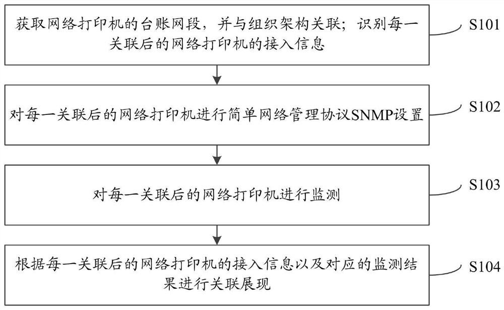
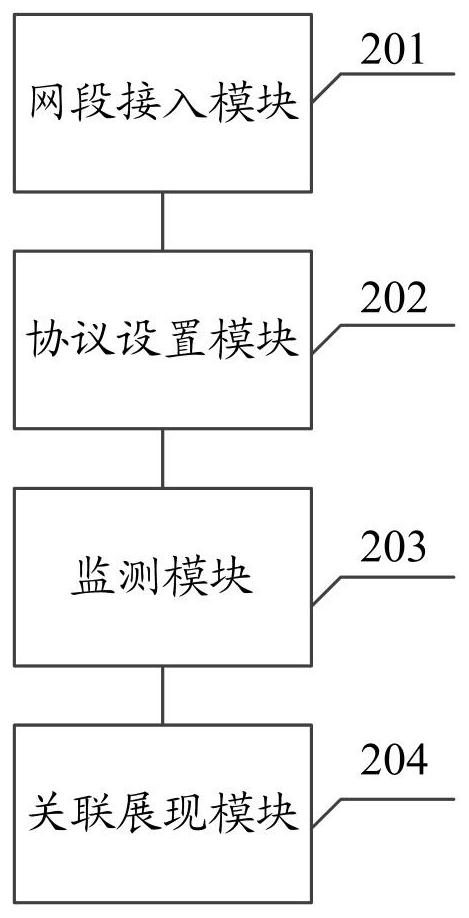
The invention relates to a network printer equipment monitoring method and system. The method comprises the following steps: acquiring a ledger network segment of a network printer, and associating the ledger network segment with an organizational structure; identifying access information of each associated network printer; the access information comprises a model, a manufacturer, a high-risk port, a service component, an application related list, a user and a department of the network printer; performing simple network management protocol (SNMP) setting on each associated network printer; each associated network printer is monitored; and performing association display according to the access information of each associated network printer and the corresponding monitoring result. According to the invention, dynamic monitoring and centralized analysis can be carried out on the whole network printer equipment, the operation condition of the printing equipment can be mastered in time, and unified monitoring management is realized.

Description

technical field [0001] The invention relates to the field of network printer device monitoring, in particular to a network printer device monitoring method and system. Background technique [0002] Network printers, as indispensable office supplies and standard computer output devices, play an increasingly important role in today's rapid growth of information. It is not difficult to find that the number of documents printed through the network in all walks of life is increasing rapidly at an unprecedented rate, but the current account of network printers in each unit is not clear, and the management of the use of consumables and the operation of the equipment itself lacks effective means and monitoring tools. In addition, most network printers have open ports, and there are also security risks such as illegal access and leakage of confidential files. [0003] The traditional printer management system is generally unique to the manufacturer and only supports its own products...

Claims


Application Information

Patent Timeline
Patent Type & Authority Applications(China)
IPC IPC(8): G06F3/12
CPCG06F3/1287G06F3/1259G06F3/1229
Inventor 周祥峰简玮侠李永健黎礼飞李俊辉王冠麟丁锋詹婉琳郑嘉欣刘思麟
Owner ZHONGSHAN POWER SUPPLY BUREAU OF GUANGDONG POWER GRID
Learn More