
Fire-fighting fireproof door capable of being rapidly replaced

A fire-proof door and fire-fighting technology, which is applied to fire-proof doors, door leaves, windows/doors, etc., can solve the problems that fire-fighting fire doors cannot be replaced quickly, and achieve the effects of enhancing fire-proofing effect, simple operation, and improving success rate

Pending Publication Date: 2022-05-27
瑞昌市宋福安全门科技有限公司
View PDF1 Cites 0 Cited by
  • Summary
  • Abstract
  • Description
  • Claims
  • Application Information

AI Technical Summary

Problems solved by technology

[0005] In order to overcome the above-mentioned shortcoming that fire doors cannot be replaced quickly, the technical problem to be solved is to provide a fire door that can be easily installed and disassembled quickly.

Method used


Image

  • Fire-fighting fireproof door capable of being rapidly replaced
  • Fire-fighting fireproof door capable of being rapidly replaced
  • Fire-fighting fireproof door capable of being rapidly replaced

Examples


Embodiment 1

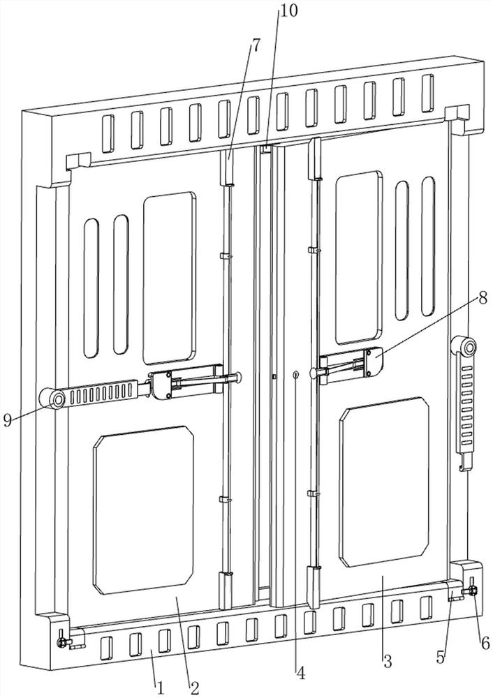
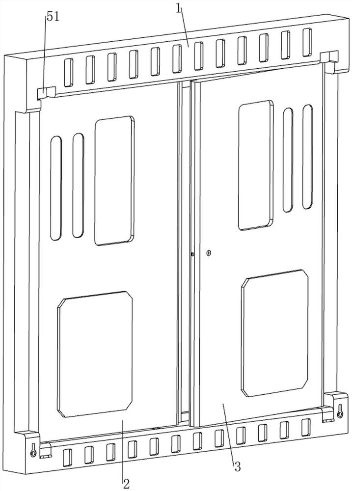
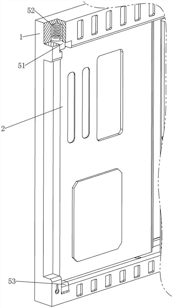
[0071] A quick-replaceable fire door, such as figure 1 As shown, it includes a door frame 1, a first door panel 2, a second door panel 3, a door lock 4, a replacement mechanism 5 and a locking mechanism 6. The door frame 1 is provided with a replacement mechanism 5, and the left side of the replacement mechanism 5 is rotatably detachable. A first door panel 2 is provided. The right side of the replacement mechanism 5 is rotatably and detachably provided with a second door panel 3. The middle of the left side of the second door panel 3 is provided with a door lock 4 by means of bolts. The door lock 4 can lock the first door panel 3. The door panel 2 and the second door panel 3, the first door panel 2 and the second door panel 3 are all high temperature resistant materials, the rear parts of the first door panel 2 and the second door panel 3 are provided with door handles by means of screws, and the lower part of the door frame 1 is provided with a door handle. Locking mechanism...

Embodiment 2

[0076] On the basis of Example 1, as figure 1 , Figure 7 , Figure 8 and Figure 9 As shown, it also includes an opening and closing mechanism 7. The opening and closing mechanism 7 includes a second fixing rod 71, a third sliding plate 72 and a third spring 73. The inner sides of the front parts of the first door panel 2 and the second door panel 3 are welded by means of welding. A second fixing rod 71 is provided. The upper and lower parts of the second fixing rod 71 are slidably provided with a third sliding plate 72. The upper and lower sides of the door frame 1 are symmetrically provided with clamping holes. The third sliding plates 72 on the upper and lower sides can be respectively locked. A third spring 73 is connected between the third sliding plate 72 and the second fixing rod 71 in the corresponding clamping hole of the door frame 1 .

[0077] During the process of closing the first door 2 and the second door 3, the second fixing rod 71, the third sliding plate ...


PUM


Abstract

The invention relates to a fire-fighting fireproof door, in particular to a fire-fighting fireproof door capable of being rapidly replaced. The invention provides the fire-fighting fireproof door which is convenient to mount and dismount and can be quickly replaced. A fire-fighting fireproof door capable of being rapidly replaced comprises a door frame and a replacing mechanism, and the replacing mechanism is arranged on the door frame; the first door plate is rotationally arranged on the left side of the replacement mechanism; the second door plate is rotationally arranged on the right side of the replacement mechanism, and the first door plate and the second door plate can be detached; the door lock is arranged in the middle of the left side of the second door plate; and the locking mechanism is arranged at the lower part of the door frame. After the first door plate and the second door plate are closed, the first door plate and the second door plate are locked through the door lock, fire and smoke can be blocked behind, the fireproof effect is achieved, and the first door plate or the second door plate can be rapidly detached by pushing the first sliding plate upwards and can be conveniently replaced.

Description

technical field [0001] The invention relates to a fire-fighting door, in particular to a fast-replaceable fire-fighting door. Background technique [0002] In some large shopping malls or high-temperature work areas, it is usually necessary to set up fire emergency passages, and fire doors usually need to be installed at the passages, so that in the event of a fire, the spread of fire and smoke can be avoided within a certain period of time, thereby gaining escape time for the disaster area personnel. . [0003] Patent application CN208184597U, published on 20181204, discloses a fire door, including a main body, a smoke outlet, a threshold and a composite layer, a door frame is arranged on the outside of the main body, and an observation window is arranged inside the main body, the door frame The inner wall of the main body is provided with a sealing ring, and the outer side of the door frame is arranged with a base body, the outer wall of the main body is movably connected...

Claims


Application Information

Patent Timeline
Patent Type & Authority Applications(China)
IPC IPC(8): E06B5/16E06B3/70
CPCE06B5/16E06B3/70E06B2003/7011
Inventor 柯柏林
Owner 瑞昌市宋福安全门科技有限公司
Learn More