Automatic stripping equipment for thin film roll material

An automatic peeling and film technology, which is applied in plastic recycling, packaging, transportation and packaging, etc., can solve the problems of position deviation and poor stability, and achieve the effect of less space, low cost and compact layout

Pending Publication Date: 2022-05-27
上海巨灵信息技术股份有限公司
View PDF0 Cites 0 Cited by
  • Summary
  • Abstract
  • Description
  • Claims
  • Application Information

AI Technical Summary

Problems solved by technology

[0003] The purpose of the present invention is to provide an automatic film peeling equipment with wide size compatibility, which can solve the problems of position deviation and poor stability during the peeling process

Method used


Image

  • Automatic stripping equipment for thin film roll material
  • Automatic stripping equipment for thin film roll material
  • Automatic stripping equipment for thin film roll material

Examples


Embodiment Construction

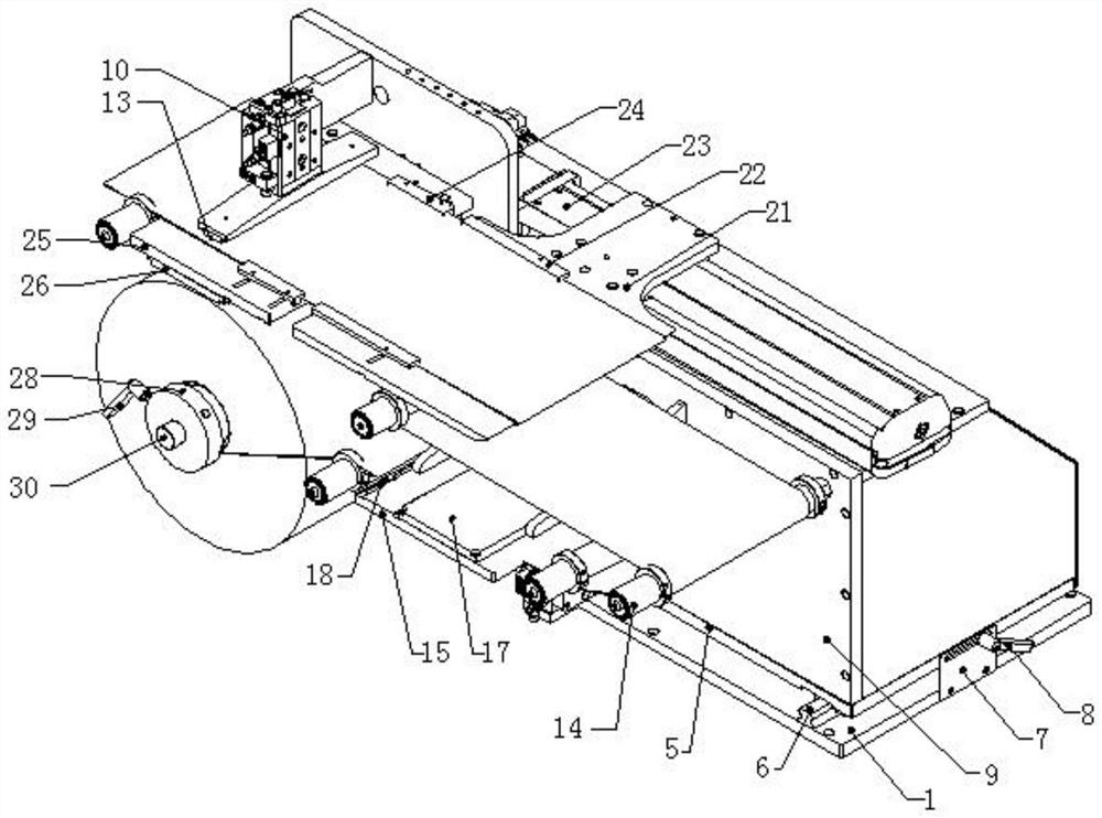
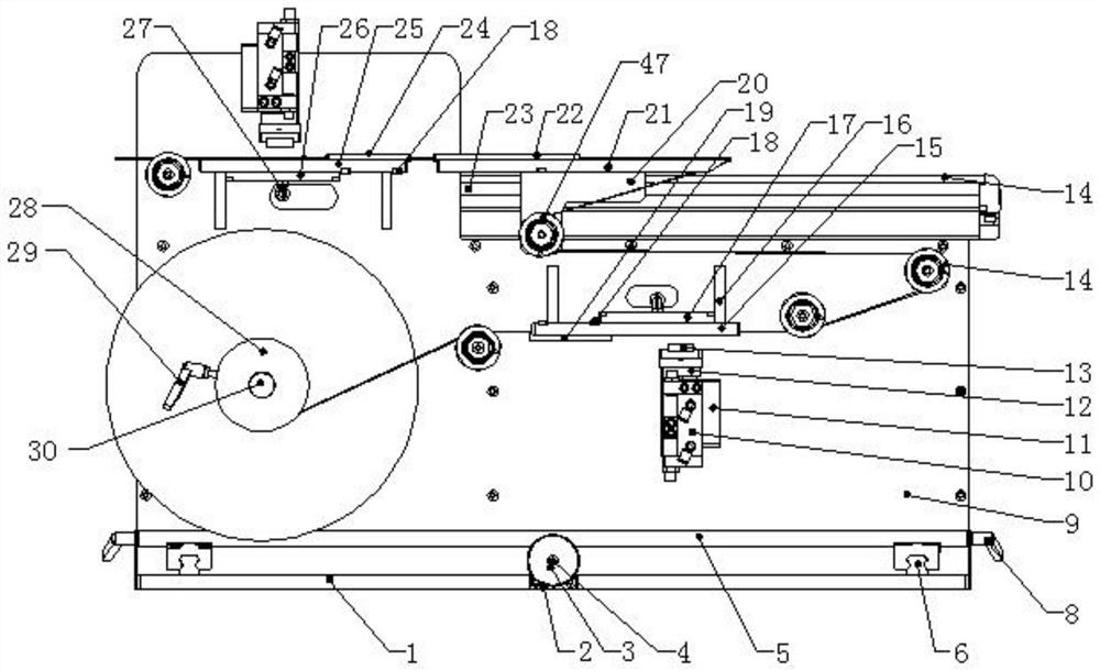
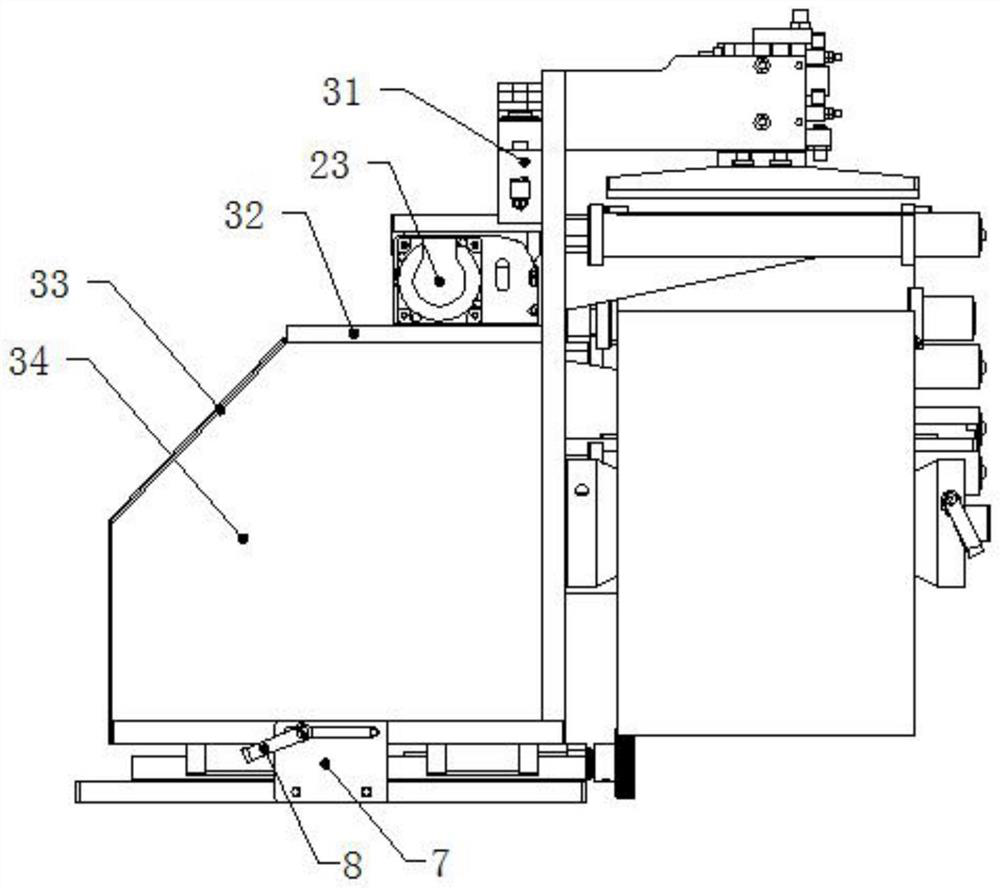
[0030] as Figure 1-5 As shown, a film coil automatic stripping device, comprising a linear rail mounting plate 1, mounting base plate 5 and main mounting plate 9, the mounting base plate 5 can be sliding through the sliding assembly can be sliding connection above the linear rail mounting plate 1, the linear rail mounting plate 1 and the left and right sides of the mounting base plate 5 are provided with a positioning adjustment plate 7 and a first fastening handle 8, the adjustment plate 7 is fixed by a screw connection to the linear rail mounting plate 1, The connecting end of the first tightening handle 8 runs through the lumbar hole of the adjustment plate 7 after being connected to the mounting base plate 5, and the tightening limit is carried out by rotating the first tightening handle 8;

[0031]The main mounting plate 9 is vertically connected to the mounting base plate 5, the main mounting plate 9 and the mounting base plate 5 are connected in the common vertical directio...


PUM


Abstract

The automatic stripping equipment comprises a linear guide rail mounting plate, a mounting bottom plate and a main mounting plate, the mounting bottom plate is slidably connected to the upper portion of the linear guide rail mounting plate, and an adjusting plate and a first fastening handle for positioning are arranged on the two sides of the mounting bottom plate; three vertical side plates are connected in the common vertical direction of the main mounting plate and the mounting bottom plate, a driving traction shaft is connected to the left side of the main mounting plate, a waste roll conical pressing block is arranged at the front end of the driving traction shaft, and the rear end of the driving traction shaft is connected with a driving device; four sets of material belt rollers, two sets of material pressing mechanisms and two sets of material belt adjusting adsorption mechanisms are arranged on the main mounting plate, a stripping servo module is connected to the module mounting plate on the upper sides of the three vertical side plates, a stripping knife is mounted on a sliding block of the stripping servo module, and a movable material belt roller is connected to the lower side of the stripping servo module. The film feeding device is compact in structure, low in cost, small in occupied space, convenient to adjust and wide in size compatibility range of film material belts.

Description

Technical field [0001] The present invention relates to the field of film production equipment, in particular to a film coil automatic stripping equipment. Background [0002] With the development of science and technology, especially the development of electronic technology, some electronic components are getting thinner and thinner, and the size of more and more types, many of which are in the form of thin films, and the assembly of products is mostly in the form of mounting. This kind of film material feeding method is generally in the form of flakes or coils, but compared to the flake feeding method, the coil incoming material has the advantages of small footprint and compact structure, so it is mainly based on coil feeding. The film is fed on a coil, first of all, it must be stripped out of the material belt, and the manual peeling and placement will contaminate the product and the efficiency is very low, so the machine is generally used to automatically peel. Many stripping...

Claims


Application Information

Patent Timeline
Patent Type & Authority Applications(China)
IPC IPC(8): B65B69/00
CPCB65B69/00Y02W30/62
Inventor 邬松韩冲李永奇蔡文刚陆彬曾德铭杨柳风
Owner 上海巨灵信息技术股份有限公司
Why Eureka
Try Eureka