Auxiliary frame for bending steel bars at top of rotary excavating pile

A technology of rotary digging piles and auxiliary frames, applied in the field of steel bar bending auxiliary frames, which can solve the problems of complex operation and large volume, and achieve the effect of simple and convenient operation

Pending Publication Date: 2022-05-27
华德明
View PDF1 Cites 0 Cited by
  • Summary
  • Abstract
  • Description
  • Claims
  • Application Information

AI Technical Summary

Problems solved by technology

[0005] In order to overcome the shortcomings of the existing pile head steel bar bending devices, which are generally large in size and complicated to operate, the purpose of the present invention is to provide an easy-to-operate steel bar bending auxiliary frame at the top of the rotary excavation pile

Method used


Image

  • Auxiliary frame for bending steel bars at top of rotary excavating pile
  • Auxiliary frame for bending steel bars at top of rotary excavating pile
  • Auxiliary frame for bending steel bars at top of rotary excavating pile

Examples


Embodiment 1

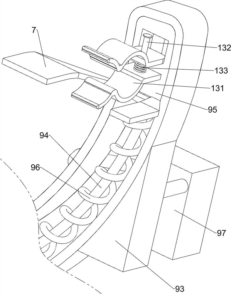
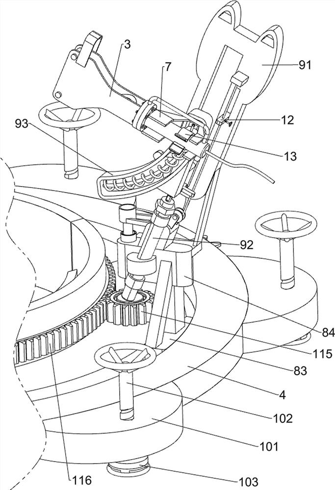
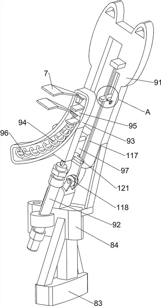
[0030] An auxiliary frame for bending and bending of steel bars at the top of a rotary excavation pile, refer to Figure 1-Figure 4 , including a first bottom plate 4, a second bottom plate 5, a contact plate 6, a limit plate 7, a moving mechanism 8 and an auxiliary mechanism 9, the first bottom plate 4 is located on the front side of the second bottom plate 5, and the rear side of the first bottom plate 4 is connected to the The front sides of the two bottom plates 5 are in contact with each other, the middle part of the rear side of the first bottom plate 4 and the middle part of the front side of the second bottom plate 5 are welded with a contact plate 6 , the first bottom plate 4 is provided with a moving mechanism 8 , and the moving mechanism 8 is provided with an auxiliary mechanism 9. Two limit plates 7 are provided on the auxiliary mechanism 9 , and the limit plates 7 can limit the support of the press brake 3 .

[0031] refer to Figure 1-Figure 3 , the moving mecha...

Embodiment 2

[0035] On the basis of Example 1, refer to Figure 1-Figure 3 , also includes a balance mechanism 10, the balance mechanism 10 includes a connecting plate 101, an adjustment screw 102 and an adjustment block 103, and three connecting plates 101 are welded at intervals between the outer lower part of the first base plate 4 and the outer lower part of the second base plate 5. The number of the plates 101 is six, the connecting plate 101 is provided with an adjusting screw 102 in a threaded manner, the upper part of the adjusting screw 102 is provided with a handle, and the lower part of the adjusting screw 102 is provided with an adjusting block 103 in a rotating manner, and the adjusting block 103 can move downward. Jack up the whole device to achieve the purpose of adjusting the angle.

[0036] When the contact plates 6 are all in contact with the rotary excavation pile 1, people can see whether the first bottom plate 4 and the second bottom plate 5 are parallel to the rotary ...


PUM


Abstract

The invention relates to a steel bar bending auxiliary frame, in particular to a rotary excavating pile top steel bar bending auxiliary frame. The invention aims to provide the rotary excavating pile top steel bar bending auxiliary frame which is convenient to operate. The rotary excavating pile top steel bar bending auxiliary frame comprises a first bottom plate, a second bottom plate, contact plates, a moving mechanism and the like, the first bottom plate is located on the front side of the second bottom plate, the rear side of the first bottom plate makes contact with the front side of the second bottom plate, and the contact plates are arranged in the middle of the rear side of the first bottom plate and the middle of the front side of the second bottom plate correspondingly; and a moving mechanism for driving the bending press to move is arranged on the first bottom plate. According to the steel bar bending device, the limiting plate can limit and support the bending machine, then people can bend steel bars through the bending machine, the air cylinder serves as driving force to drive the bending machine to move upwards to be away from the steel bars, then the sliding block is manually moved, the bending machine can be driven to move to the position above the next steel bar, and operation is easy and convenient.

Description

technical field [0001] The invention relates to an auxiliary frame for bending of steel bars, in particular to an auxiliary frame for bending and bending of steel bars at the top of a rotary excavation pile. Background technique [0002] During the construction of bored piles, after the pile head is transferred and transported, it is necessary to use a hydraulic steel bending machine to quickly make a steel elbow at the pile head to ensure the concentric force of the steel bar and reduce the concrete cracks caused by the tensile deformation of the steel bar. [0003] Patent application CN113059081A, published on 20210702, discloses a pile head steel bar bending device with an accurate bending direction, including a positioning box, and the positioning box is provided with a positioning device for positioning the center position of the pile head from four directions, The side of the positioning box away from the ground is provided with a rotating device that can freely rotate...

Claims


Application Information

Patent Timeline
Patent Type & Authority Applications(China)
IPC IPC(8): B21F1/00
CPCB21F1/004
Inventor 华德明
Owner 华德明
Why Eureka
Try Eureka