


Quick Research
Generate reliable direction feasibility study reports for your R&D in just a few steps.

Technical Q&A
Discover and master advanced knowledge NOW. Basics, ideas, possibilities, all at once.

Find Solutions
As an expert in R&D theories, this can generate solutions to your technical problems instantly.

Evaluate Feasibility
Analyze your overall solution with one click, know your potential R&D risks in advance.

Monitor Landscape
Get weekly tech updates, stay abreast of the latest tech innovations and key insights.
A power distribution cabinet with overheating dynamic warning
A dynamic early warning and power distribution cabinet technology, which is applied in the direction of measuring heat, electrical components, and parts of thermometers, etc., can solve problems such as limited clearance of cooling holes, untimely cooling, and potential safety hazards, so as to increase the cooling effect and improve cooling speed and reduce potential safety hazards
- Summary
- Abstract
- Description
- Claims
- Application Information
AI Technical Summary
Problems solved by technology
Method used
Image


Examples
Embodiment 1
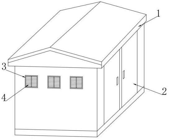
[0038] see figure 1 , a power distribution cabinet with dynamic overheating warning, comprising a cabinet body 1, a cabinet door 2 is installed on the cabinet body 1, a plurality of evenly distributed heat dissipation windows 3 are fixedly inlaid on the side ends of the cabinet body 1, and the heat dissipation windows 3 are internally connected with A plurality of evenly distributed heat sink spacers 4 .
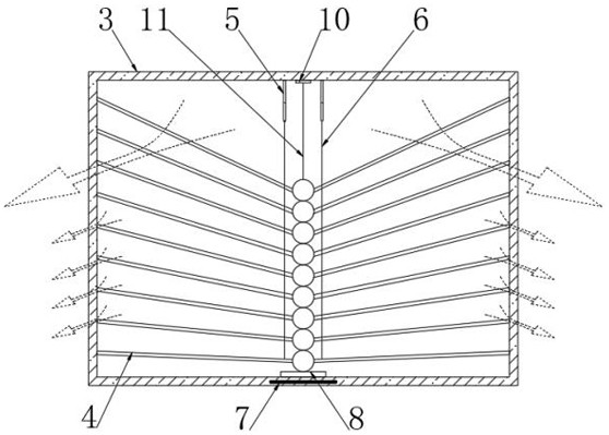
[0039] see Figure 2-3, two symmetrical electric push rods 5 and a tension sensor 10 are installed at the top of the heat dissipation window 3. The tension sensor 10 is located in the middle of the two electric push rods 5, and between the lower end of the electric push rod 5 and the plurality of heat sink spacers 4 Both are fixedly connected with a position control rope 6, a pull rope 11 is fixedly connected between the lower end of the tension sensor 10 and the middle of the uppermost heat sink spacer 4, and a self-resetting elastic switch 8 is electrically connected to t...
Embodiment 2
[0051] see Figure 8 , the photosphere 9 includes an outer layer 91, an inner light-emitting layer 92 located in the outer layer 91, and a plurality of uniformly distributed limit ropes 93 connected between the inner light-emitting layer 92 and the outer layer 91. The outer layer 91 and the inner light-emitting layer A plurality of counterweight moving balls 12 are placed between 92, the inner luminescent layer 92 is filled with fluorescent liquid and inert gas, the filling degree of the fluorescent liquid is not less than 60%, and the inner luminescent layer 92 is a transparent elastic structure with many protrusions on the outer surface. , when the light ball 9 moves along the thermally variable elastic bar 43, the internal counterweight moving ball 12 is in a dynamic state, which can generate a certain vibration force on the inner light-emitting layer 92, so that the internal fluorescent liquid is more affected The vibration of the emitted light makes the dynamic warning ef...
PUM
 Abstract
Description
Claims
Application Information
 - R&D Engineer
- R&D Manager
- IP Professional
- Industry Leading Data Capabilities
- Powerful AI technology
- Patent DNA Extraction
Browse by: Latest US Patents, China's latest patents, Technical Efficacy Thesaurus, Application Domain, Technology Topic, Popular Technical Reports.
© 2024 PatSnap. All rights reserved.Legal|Privacy policy|Modern Slavery Act Transparency Statement|Sitemap|About US| Contact US: help@patsnap.com