Stretching device capable of continuously stretching PVC (polyvinyl chloride) film

A technology of stretching device and driving roller, which is applied in the field of PVC film sustainable stretching stretching device, can solve the problems of inability to realize continuous work of PVC film and low work efficiency, and achieve ingenious structural design, time saving and uniform force Effect

Active Publication Date: 2022-05-24
江苏永润包装材料有限公司
View PDF14 Cites 0 Cited by
  • Summary
  • Abstract
  • Description
  • Claims
  • Application Information

AI Technical Summary

Problems solved by technology

[0006] In this technical solution, a neck pressure device is provided to stretch the PVC film, and the stretching is realized by setting a concave drum and a matching drum drum. The fixing of the overall PVC film is more convenient, and the stretching is also more convenient. However, the continuous operation of the PVC film cannot be realized in this technical scheme, resulting in low work efficiency

Method used


Image

  • Stretching device capable of continuously stretching PVC (polyvinyl chloride) film
  • Stretching device capable of continuously stretching PVC (polyvinyl chloride) film
  • Stretching device capable of continuously stretching PVC (polyvinyl chloride) film

Examples


Embodiment 1

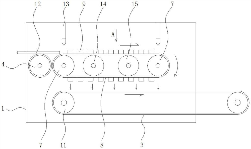
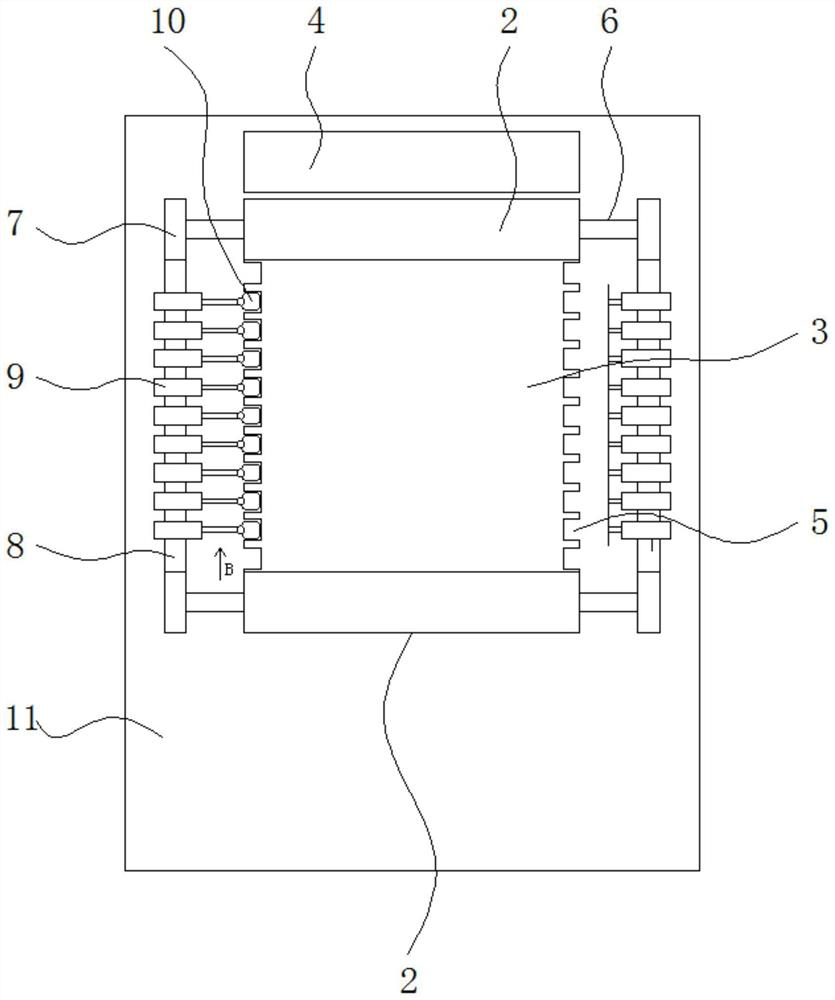
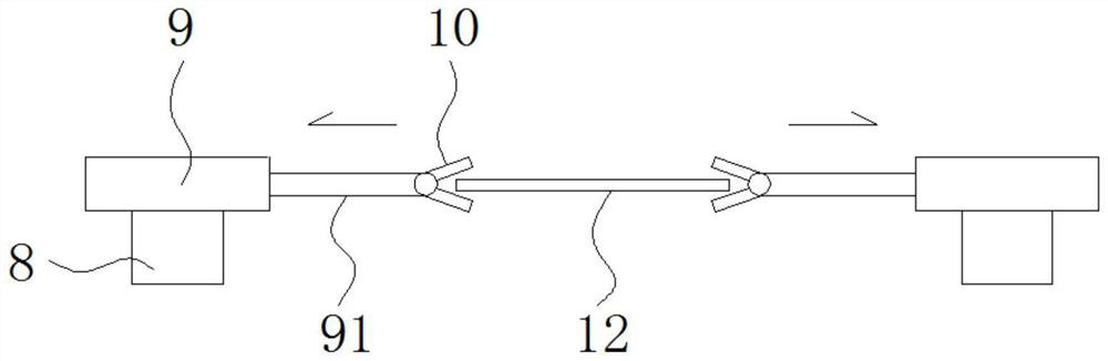
[0031] like figure 1 , figure 2 and image 3 As shown in the figure, a PVC film can be continuously stretched and stretched, including a drying chamber 1, and two driving rollers 2 are also arranged in the drying chamber 1, and a conveyor belt 3 is correspondingly installed between the two driving rollers 2. The width of the belt 3 corresponds to the width of the transmission roller 2, and the left side of the drying chamber 1 is also installed with a feeding roller 4 corresponding to the height of the conveyor belt 3. The feeding roller 4 can transfer the PVC film 12 to the conveyor belt 3. , the PVC film 12 is transported forward with the conveyor belt 3 .

[0032] The edge positions on both sides of the conveyor belt 3 are also provided with evenly spaced clamping gaps 5, the roller shafts 6 of the two drive rollers 2 are extended to both sides, and the ends of the roller shafts 6 are also equipped with corresponding drive sprockets 7. , a transmission sprocket 7 is cor...

Embodiment 2

[0041] like figure 1 , figure 2 and image 3 As shown in the figure, a PVC film can be continuously stretched and stretched, including a drying chamber 1, and two driving rollers 2 are also arranged in the drying chamber 1, and a conveyor belt 3 is correspondingly installed between the two driving rollers 2. The width of the belt 3 corresponds to the width of the transmission roller 2, and the left side of the drying chamber 1 is also installed with a feeding roller 4 corresponding to the height of the conveyor belt 3. The feeding roller 4 can transfer the PVC film 12 to the conveyor belt 3. , the PVC film 12 is transported forward with the conveyor belt 3 .

[0042] The edge positions on both sides of the conveyor belt 3 are also provided with evenly spaced clamping gaps 5, the roller shafts 6 of the two drive rollers 2 are extended to both sides, and the ends of the roller shafts 6 are also equipped with corresponding drive sprockets 7. , a transmission sprocket 7 is cor...


PUM


Abstract

The invention discloses a PVC film sustainable stretching device which comprises a drying chamber, two transmission rollers are further arranged in the drying chamber, a conveying belt is correspondingly installed between the two transmission rollers, the conveying belt corresponds to the transmission rollers in width, and a feeding roller corresponding to the conveying belt in position and height is further installed on the left side of the drying chamber. The feeding roller can convey the PVC film to the conveying belt, and the PVC film is conveyed forwards along with the conveying belt. The whole structure is arranged in the drying chamber, in the stretching and transferring process after clamping and fixing, the stretched PVC film is dried and cured through the time difference, and time is saved; the transmission chain wheels are connected and installed on the transmission rollers on the two sides, the transmission chain is installed on the transmission chain wheels, the reciprocating type stretching mechanism is installed on the transmission chain, synchronous movement of the reciprocating type stretching mechanism and the transmission rollers can be guaranteed, and continuous feeding of PVC films can be achieved through the additionally-arranged feeding rollers.

Description

technical field [0001] The invention relates to the technical field of film stretching equipment, in particular to a sustainable stretching and stretching device for PVC films. Background technique [0002] In the prior art, the PVC film needs to be stretched by stretching in the subsequent production process, so as to adjust the thickness of the PVC film. The PVC film is fixed, and then the edge of the PVC film is stretched by clamping jaws and other tools. [0003] For example: Publication (Announcement) No.: CN212422162U patent document discloses "a stretching device for PVC film", in this technical solution, a front plate and a rear plate are arranged, and the distance between the front plate and the rear plate is along the film conveying direction. A take-off roll, a stretching mechanism and a cooling roll are arranged in sequence. The inside of the take-off roll is hollow. The stretching mechanism includes a first stretching roll, a moving roll and a second stretching...

Claims


Application Information

Patent Timeline
Patent Type & Authority Applications(China)
IPC IPC(8): B65H20/06B29C55/02B29C35/02B23K26/38B23K26/70
CPCB65H20/06B29C55/02B29C35/02B23K26/38B23K26/702B65H2701/1752B29L2007/00Y02P70/10
Inventor 鲍凯文鲍鹏宇张利阳
Owner 江苏永润包装材料有限公司
Why Eureka
Try Eureka