
Cup overturning device

A technology for turning cups and packages, which is applied in packaging, transportation and packaging, climate sustainability, etc. It can solve the problems of low production efficiency and easily damaged packages, and achieve the effect of improving the efficiency of cup turning

Pending Publication Date: 2022-05-24
HANGZHOU ZHONGYA MACHINERY CO LTD
View PDF0 Cites 1 Cited by
  • Summary
  • Abstract
  • Description
  • Claims
  • Application Information

AI Technical Summary

Problems solved by technology

[0002] At present, when the filling machine on the market performs the cup turning operation, it usually adopts a clamping structure to clamp both sides of the package on the input conveying assembly, and then moves and turns over the clamping structure so that the package falls on the On the output transmission component, this structure is easy to damage the package when clamping the package, and at the same time, only one row of packages can be clamped and turned over at a time, and the production efficiency is low

Method used


Image

  • Cup overturning device
  • Cup overturning device
  • Cup overturning device

Examples


Embodiment 1

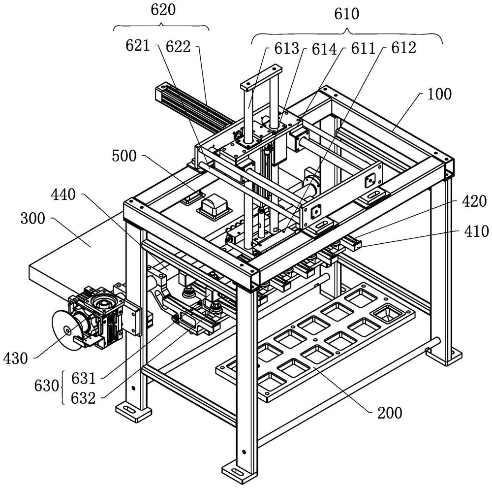
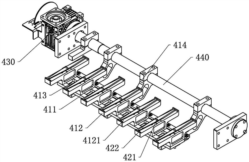
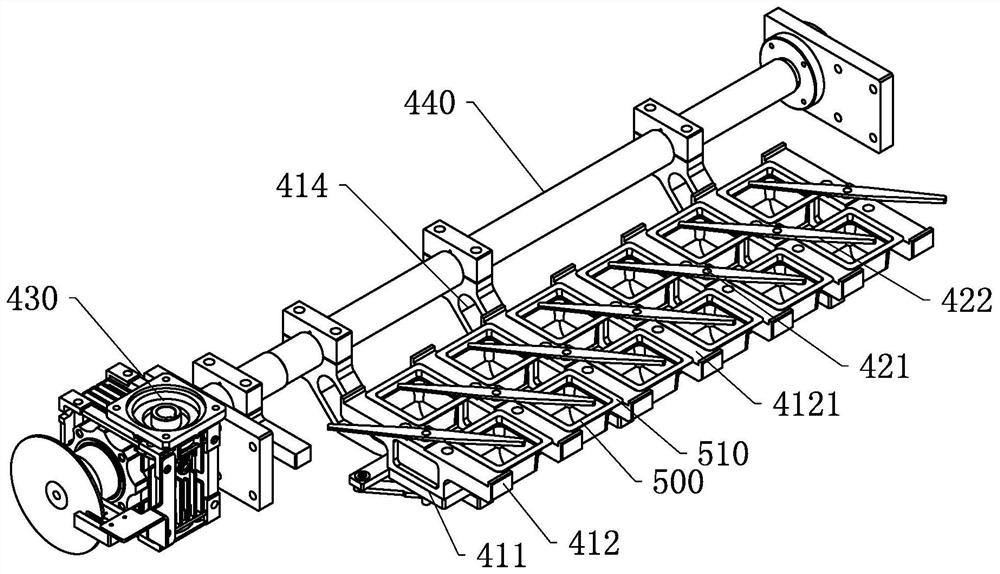
[0045] A cup turning device, such as Figure 1 to Figure 4 As shown, it includes a mounting bracket 100, an input conveying assembly 200, a handling assembly, a turning assembly, and an output conveying assembly 300. The handling assembly and the turning assembly are arranged on the mounting bracket 100, and the input conveying assembly 200 and the output conveying assembly 300 are respectively located on the opposite sides of the turning assembly. On both sides, the carrying assembly is located above the input conveying assembly 200 and the turning assembly, and the bottom of the carrying assembly is provided with a suction cup assembly 630 .

[0046] The flip assembly in this embodiment includes a support mechanism 410, a limit mechanism 420, a first drive mechanism 430 and a rotating shaft 440. The first drive mechanism 430 is fixedly installed on the mounting bracket 100, and the rotating shaft 440 is rotatably connected to the mounting bracket 100. The output shaft of a d...

Embodiment 2

[0058] The difference between this embodiment and the first embodiment is that the transmission shaft in this embodiment is connected to the end of the limit rod, so that when the limit rod rotates, it will swing into the accommodating groove on one side of the support plate as a whole, That is, the limit rods on each support plate shield the accommodating grooves on one side of the support plate respectively, so as to limit the position of the package in the accommodating groove. Prevent collision between limit rods, stable and reliable operation.

Embodiment 3

[0060] The difference between this embodiment and the first embodiment is that the limiting mechanism in this embodiment includes a blocking rod arranged on the top of the supporting mechanism and a linear cylinder set on the side of the supporting mechanism. The shielding rod can be stored in the upper part of the support mechanism to avoid the accommodating groove or move to the top of the accommodating groove to shield the packages in all the installation grooves at the same time.


PUM


Abstract

The invention discloses a cup overturning device which comprises an input conveying assembly, a carrying assembly, an overturning assembly and an output conveying assembly, the carrying assembly is located above the input conveying assembly and the overturning assembly, a suction cup assembly is arranged at the bottom of the carrying assembly, and the carrying assembly moves a packaging piece on the input conveying assembly to the overturning assembly through the suction cup assembly; the input conveying assembly and the output conveying assembly are located on the two sides of the overturning assembly correspondingly, and the overturning assembly rotates to drive packaging pieces on the overturning assembly to be overturned to the output conveying assembly. According to the cup overturning device, the packaging pieces are driven to overturn and move to the output conveying assembly through the overturning assembly, the multiple rows of packaging pieces on the input conveying assembly can be moved to the overturning assembly at the same time through the carrying assembly, the multiple rows of packaging pieces can be overturned at the same time through one-time overturning of the overturning assembly, the packaging pieces do not need to be moved and overturned row by row, and the cup overturning efficiency is improved.

Description

technical field [0001] The invention belongs to the field of filling machines, in particular to a cup turning device. Background technique [0002] At present, when the filling machine on the market performs the cup turning operation, the clamping structure is usually used to clamp the two sides of the package on the input conveying assembly, and then the clamping structure is moved and turned over so that the package falls on the On the output conveying assembly, the structure is easy to damage the packaged parts when clamping the packaged parts, and at the same time, only one row of the packaged parts can be clamped and turned over, resulting in low production efficiency. SUMMARY OF THE INVENTION [0003] The technical problem to be solved by the present invention is to provide a cup turning device to solve at least one of the above problems. [0004] In order to solve the above-mentioned technical problems, the present invention adopts the following technical solutions...

Claims


Application Information

Patent Timeline
Patent Type & Authority Applications(China)
IPC IPC(8): B65B61/00B65G47/248B65G47/91
CPCB65B61/00B65G47/248B65G47/912B65G47/918Y02P70/50
Inventor 史中伟史正唐官仁唐铁权
Owner HANGZHOU ZHONGYA MACHINERY CO LTD
Learn More