
Antenna and terminal device

A technology for terminal equipment and antennas, which is applied to antennas, resonant antennas, and mid-position feeds between antenna endpoints. It can solve problems such as the inability to achieve dual-frequency characteristics and no dual-frequency resonance characteristics.

Active Publication Date: 2022-05-13
HUAWEI TECH CO LTD
View PDF10 Cites 0 Cited by
  • Summary
  • Abstract
  • Description
  • Claims
  • Application Information

AI Technical Summary

Problems solved by technology

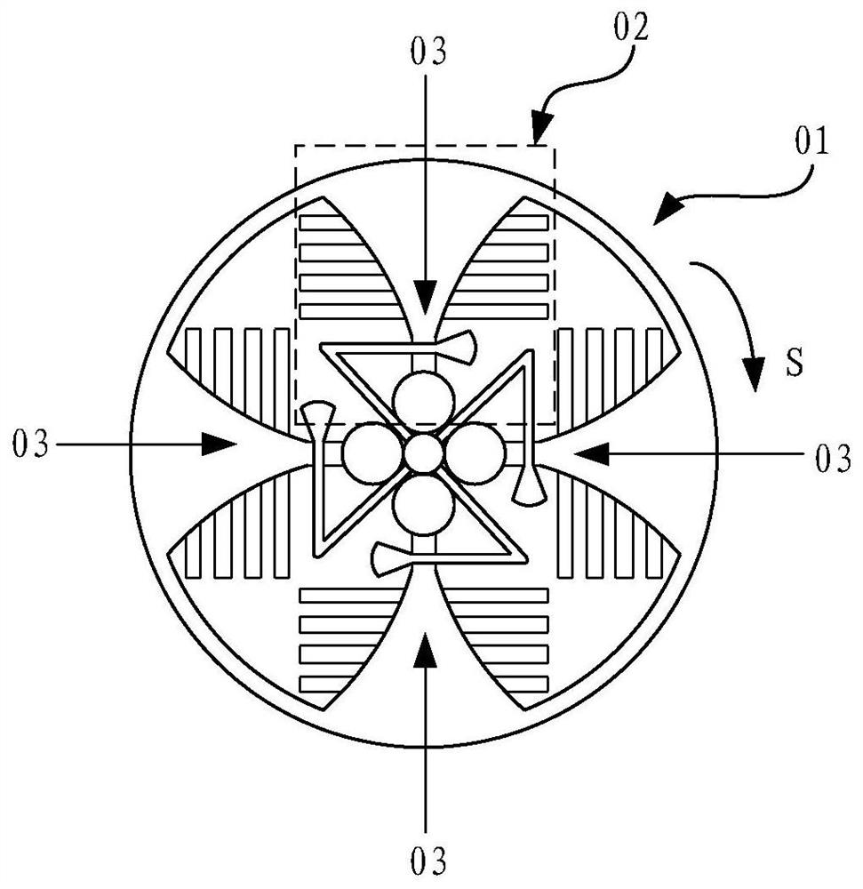
[0005] Currently as figure 1 The gradient slot antennas shown are all single-frequency antennas, which can only cover 2.4G or 5G bandwidth, without dual-frequency resonance characteristics, and thus cannot realize the dual-frequency characteristics of 2.4G and 5G in the common radiator state

Method used


Image

  • Antenna and terminal device
  • Antenna and terminal device
  • Antenna and terminal device

Examples


Embodiment Construction

[0057] The technical solutions in the embodiments of the present application will be described in detail below in conjunction with the accompanying drawings.

[0058] In order to facilitate the understanding of the technical solution, the technical terms involved in this application are explained below.

[0059] Wireless fidelity (wireless fidelity, WIFI): It is a wireless network transmission technology that converts wired network signals into wireless signals, which can be received by related terminal equipment that supports its technology. WIFI can also be expressed as "Wi-Fi", "WiFi", "Wifi" or "wifi". A terminal device capable of supporting wifi connection needs to be equipped with a wifi antenna for sending and receiving signals. The working frequency band of the wifi antenna includes 2.4G (2.4GHz~2.5GHz), the antenna working in this frequency band can be called wifi2.4G, or 2.4G wifi, and the working frequency band also includes 5G (5.15GHz~5.85GHz), Antennas working ...


PUM


Abstract

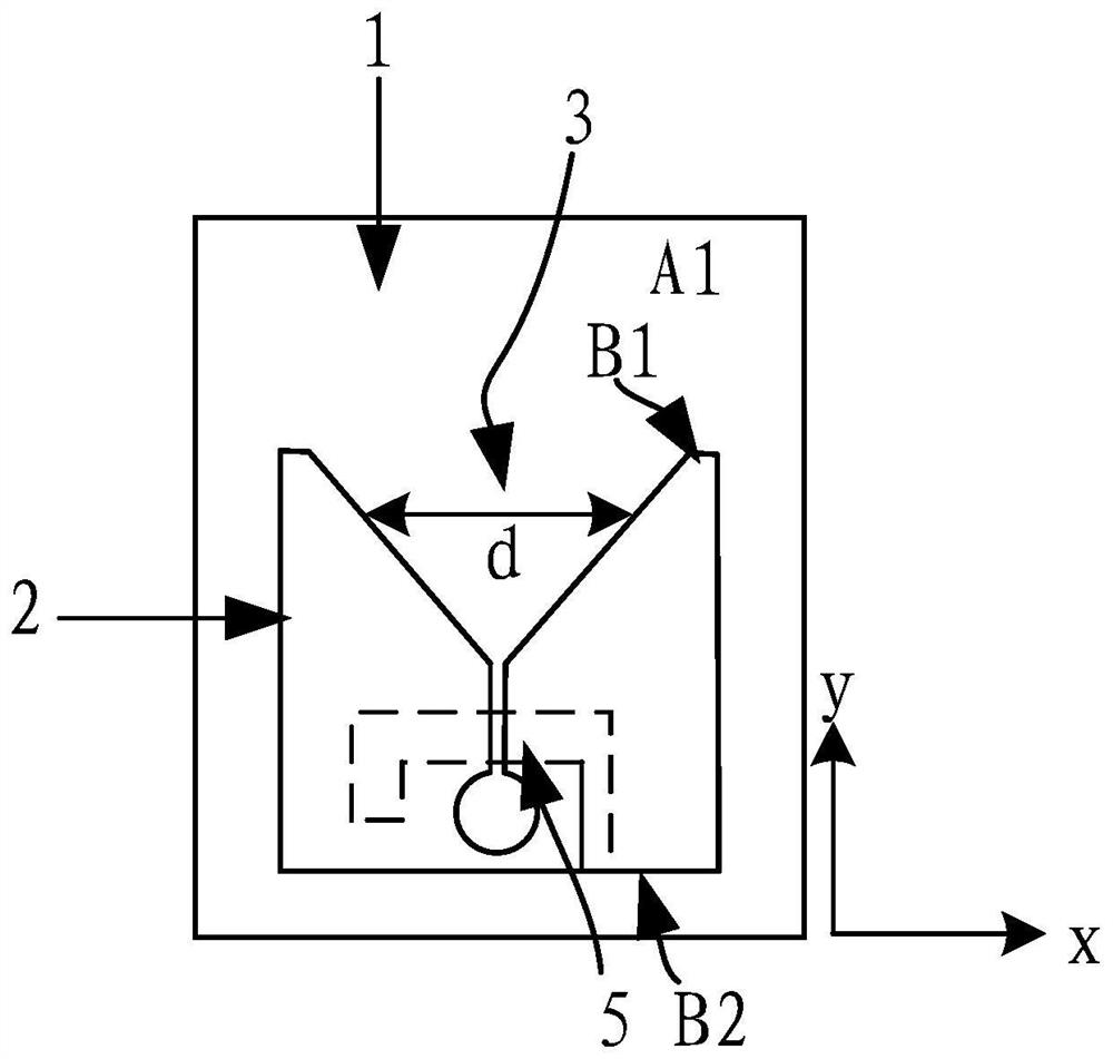
The invention provides an antenna and terminal equipment, and relates to the technical field of wireless communication. The antenna comprises a dielectric plate, a radiator, a feed network, a tapered slot and a first parasitic branch, the radiator and the feed network are both formed on the surface of the dielectric plate, and the feed network is used for coupled feeding of the radiator; the tapered slot is formed in the radiator; the first parasitic branch is located in the tapered slot, one end of the first parasitic branch is connected with the radiator, and the other end extends towards the opening direction of the tapered slot; the radiator and the first parasitic branch can transmit a signal of a first frequency band and a signal of a second frequency band different from the first frequency band.

Description

technical field [0001] The present application relates to the technical field of wireless communication, and in particular to an antenna and a terminal device. Background technique [0002] Wi-Fi (Wireless Fidelity) is a technology that allows a terminal equipment (customer premise equipment, CPE) to connect to a wireless local area network (WLAN), and Wi-Fi performance is one of the main performances of the terminal equipment. Design a quasi-isotropic antenna to increase the radiation coverage, improve the throughput efficiency in the vicinity of the original radiation zero point (including the jump layer), and make the radiation performance in all directions tend to be flat. In this case, it can Improve the competitiveness of terminal equipment. [0003] figure 1 The shown tapered slot antenna 01 (also known as tapered slot line antenna) is an antenna structure commonly used in terminal equipment at present. Radiate electromagnetic energy. [0004] These multiple anten...

Claims


Application Information

Patent Timeline
Patent Type & Authority Applications(China)
IPC IPC(8): H01Q1/38H01Q1/50H01Q9/16H01Q5/20H01Q5/10H01Q5/378
CPCH01Q1/38H01Q1/50H01Q9/16H01Q5/20H01Q5/10H01Q5/378
Inventor 秦江弘张琛李肖峰聂成成张晓璐
Owner HUAWEI TECH CO LTD
Learn More