Multifunctional sampling device and control method thereof

A sampling device and control method technology, applied in sampling device, program control, computer control and other directions, can solve the problems of waste of resources, fluid leakage, poor economy of system isolation, etc., to reduce labor intensity, improve accuracy, The effect of increasing usability

Pending Publication Date: 2022-05-13
JIANGSU XUTANG POWER GENERATION
View PDF0 Cites 0 Cited by
  • Summary
  • Abstract
  • Description
  • Claims
  • Application Information

AI Technical Summary

Problems solved by technology

[0002] In daily production and life, many sampling devices have a single function and cannot be replaced. When testing other functions of liquids, multiple devices are often required, which is likely to cause waste of resources. For example, many valves and other similar fluid cut-off devices are due to Aging, blowing erosion and other reasons cause a small amount of fluid leakage. There are various influencing factors for the shut-off device to stop the system or isolate it for repair or replacement. For example, the system cannot be isolated, and the system isolation is less economical. However, in actual operation, it is easy to cause pollution on the production site. If the fluid is a dangerous product or an environmental pollution medium, the method of connecting and draining the leaking fluid will be greatly restricted. Hole injection method realizes complete plugging, valves and other fluid cut-off devices are blocked at one time, there is no possibility of reuse and repair, and professional leak plugging personnel are required to operate, which is risky and expensive

Method used


Image

  • Multifunctional sampling device and control method thereof
  • Multifunctional sampling device and control method thereof
  • Multifunctional sampling device and control method thereof

Examples


Embodiment Construction

[0047] In order to make the purpose, technical solutions and advantages of the embodiments of the present invention more clear, the technical solutions in the embodiments will be clearly and completely described below in conjunction with the drawings in the embodiments of the present invention. The following embodiments are used to illustrate the present invention , but not to limit the scope of the present invention.

[0048] In the description of the present invention, it should be noted that the terms "upper", "lower", "front", "rear", "left", "right", "vertical", "inner", "outer" etc. The indicated orientation or positional relationship is based on the orientation or positional relationship shown in the drawings, and is only for the convenience of describing the present invention and simplifying the description, rather than indicating or implying that the referred device or element must have a specific orientation, or in a specific orientation. construction and operation, ...


PUM


Abstract

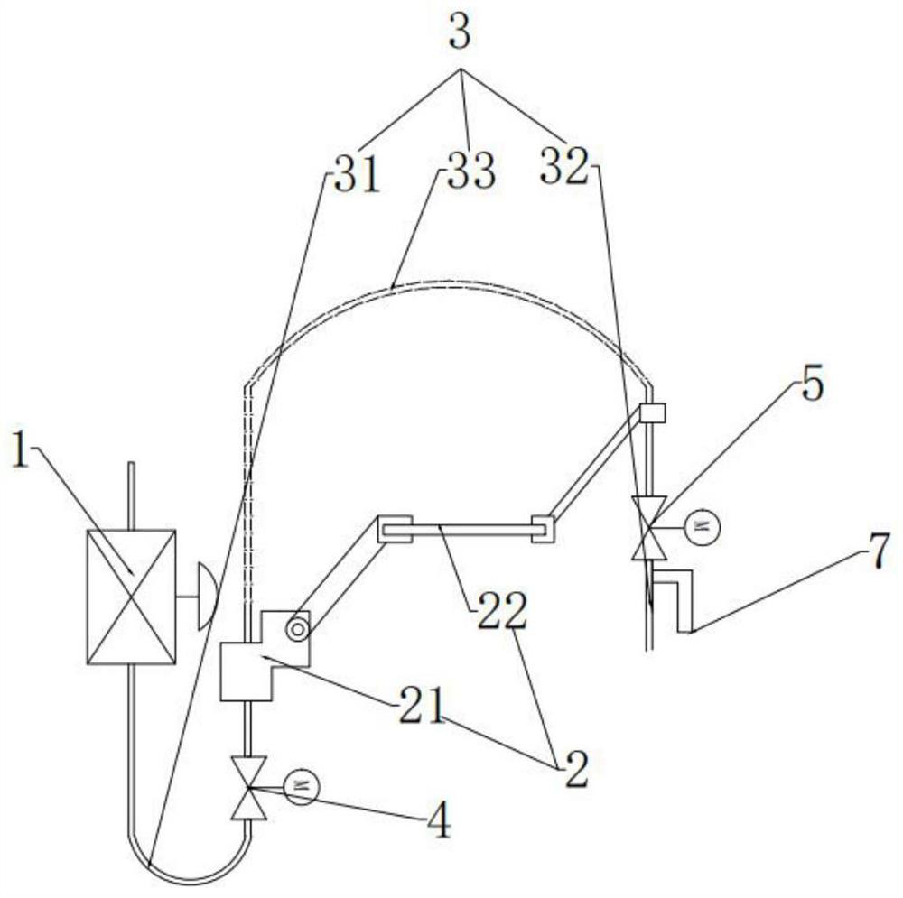
The invention discloses a multifunctional sampling device. The multifunctional sampling device comprises a sampling valve, a liquid outlet pipe and a driving device, the sampling valve comprises a liquid inlet and a liquid outlet; the liquid outlet pipe comprises a first pipe section and a second pipe section, an inlet of the first pipe section is communicated with a liquid outlet of the sampling valve, and one end of the second pipe section is a liquid outlet of the liquid outlet pipe; the driving device is arranged between the first pipe section and the second pipe section and drives the second pipe section to move relative to the first pipe section. The driving device is additionally arranged on the sampling device, during liquid sampling, sampling intellectualization can be achieved, the labor intensity is reduced, the sampling accuracy of the sampling device is improved, by arranging the driving device, the environment of a production site is prevented from being polluted or workers are prevented from being damaged, sampling is convenient, and the sampling efficiency is improved. The device is intelligent and diversified in function, and is simple in structure and low in cost.

Description

technical field [0001] The invention belongs to the field of liquid sampling, and in particular relates to a multifunctional sampling device and a control method thereof. Background technique [0002] In daily production and life, many sampling devices have a single function and cannot be replaced. When testing other functions of liquids, multiple devices are often required, which is likely to cause waste of resources. For example, many valves and other similar fluid cut-off devices are due to Aging, blowing erosion and other reasons cause a small amount of fluid leakage. There are various influencing factors for the shut-off device to stop the system or isolate it for repair or replacement. For example, the system cannot be isolated, and the system isolation is less economical. However, in actual operation, it is easy to cause pollution on the production site. If the fluid is a dangerous product or an environmental pollution medium, the method of connecting and draining the...

Claims


Application Information

Patent Timeline
Patent Type & Authority Applications(China)
IPC IPC(8): G01N1/10G05B19/042G05B19/05
CPCG01N1/10G05B19/0423G05B19/054
Inventor 王翔沈学忠梁梅秦兴桥曹开轩
Owner JIANGSU XUTANG POWER GENERATION
Why Eureka
Try Eureka