
Plasma fly ash melting device and use method thereof

A melting device and plasma technology, applied in the direction of combustion method, combustion type, lighting and heating equipment, etc., can solve the problems of incomplete melting, increased energy consumption, light specific gravity of fly ash, etc., achieve good melting effect, facilitate combustion and Decomposition, the effect of reducing the content of harmful substances

Inactive Publication Date: 2022-05-13
深圳市泰美瑞环保科技有限公司
View PDF0 Cites 0 Cited by
  • Summary
  • Abstract
  • Description
  • Claims
  • Application Information

AI Technical Summary

Problems solved by technology

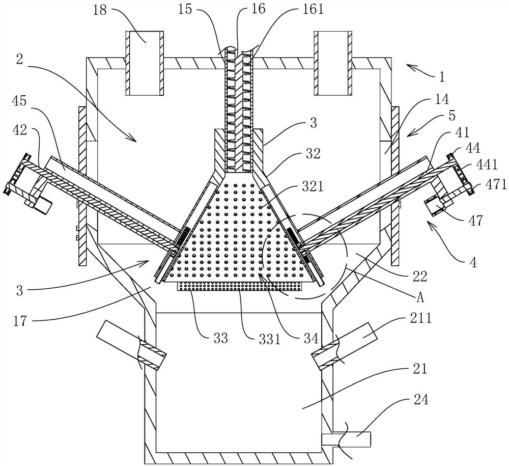
[0004] In the process of implementing the present application, the inventors found that there are at least the following problems in this technology: the specific gravity of fly ash is light, and it will be granulated with additives before entering the accommodation chamber 2 to become fine particles. In the receiving bin above the furnace
The temperature of the section above the melting zone 21 of the housing chamber 2 is lower than that of the melting zone 21. When feeding, the fly ash particles are more concentrated when they fall and may accumulate or even pile up on the top of the melting zone 21. The inside of the piled part of the fly ash particles is heated more Less, resulting in the need to increase energy consumption or the phenomenon of incomplete melting

Method used


Image

  • Plasma fly ash melting device and use method thereof
  • Plasma fly ash melting device and use method thereof
  • Plasma fly ash melting device and use method thereof

Examples


Embodiment Construction

[0048] The following is attached Figure 1-6 The application is described in further detail.

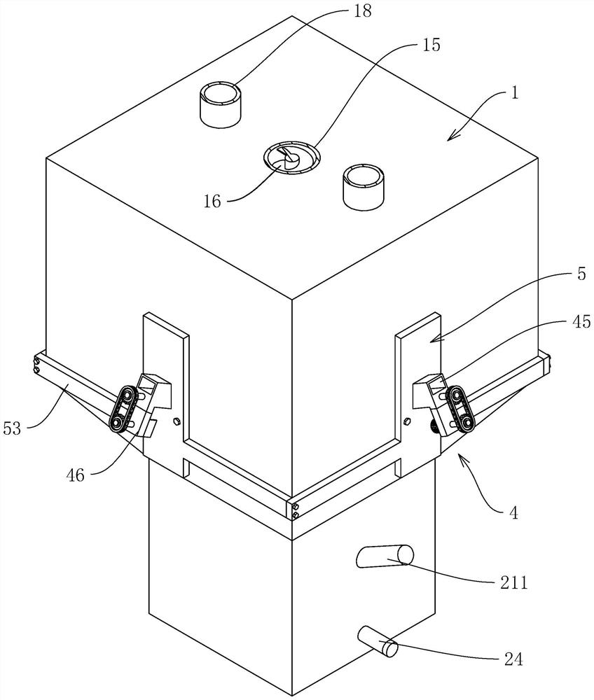
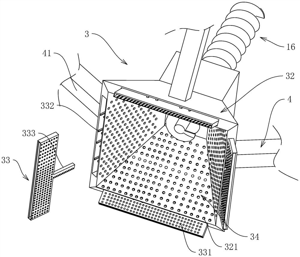
[0049] The embodiment of the present application discloses a plasma fly ash melting device. refer to figure 1 and figure 2 , a plasma fly ash melting device includes a melting furnace body 1, the melting furnace body 1 includes a housing 11 and a housing chamber 2 in the middle for melting fly ash particles, the bottom of the housing chamber 2 is provided with a melting zone 21, the melting zone A plurality of plasma torches 211 are arranged on the side wall of 21, and the fly ash particles can become molten glass after being heated by the plasma torches 211 in the melting zone 21, and a discharge pipe 24 is provided at the bottom of the melting zone 21 for Discharge the treated fly ash particles. The top of the accommodation chamber 2 is connected with a feed pipe 15 for feeding and gas outlet pipes 18 located on both sides of the feed pipe 15, and an air supply seat 4 communi...


PUM


Abstract

The invention discloses a plasma fly ash melting device and a using method thereof, and relates to the technical field of garbage disposal technology.The plasma fly ash melting device comprises a melting furnace body, a melting furnace body shell and a containing cavity, a melting area is arranged at the bottom of the containing cavity, a feeding pipe and an air outlet pipe are arranged at the top of the containing cavity, and a plasma torch is arranged on the side wall of the melting area; a discharging pipe is arranged at the bottom of the melting area, an auger is rotationally arranged in the feeding pipe, a first driving source for driving the auger to rotate is arranged on the melting furnace body, and the containing cavity comprises an operation area and is provided with a shielding cover; the shielding cover comprises a plurality of shielding plates and a bulk material cavity, the shielding plates are connected with an air supply seat, and first vent holes are uniformly formed in one sides of the shielding plates; the shielding plate is slidably provided with an extension plate, second vent holes are evenly formed in the inner wall of the extension plate, and an adjusting mechanism is arranged in the melting furnace body. When the plasma fly ash melting furnace is used, the energy of the plasma torch can be reduced, and fly ash particles can be melted more thoroughly.

Description

technical field [0001] The present application relates to the technical field of waste treatment technology, in particular to a plasma fly ash melting device and its use method. Background technique [0002] The common treatment methods of garbage include incineration. Incineration can reduce the weight of garbage by 70% and reduce the volume by 90%. However, the secondary pollution caused by incineration is also very serious. The garbage after incineration includes a large amount of fly ash, which contains Heavy metals, a large amount of oxides and inorganic salts, and some toxic substances such as dioxins. The common way to deal with fly ash includes using a plasma fly ash melting device to decompose the fly ash into a molten glass-like substance after cooling. It can be reused in construction, municipal and other fields, and has a good treatment effect. [0003] refer to Figure 7 , is a kind of plasma fly ash melting furnace in the related art, comprises shell 11 and th...

Claims


Application Information

Patent Timeline
Patent Type & Authority Applications(China)
IPC IPC(8): F23G7/00F23G5/08F23G5/44
CPCF23G7/00F23G5/085F23G5/444F23G5/44F23G2204/201F23G2209/30F23G2205/121
Inventor 王鑫
Owner 深圳市泰美瑞环保科技有限公司
Learn More