Plastic pipe connecting structure for hydraulic engineering construction
A connection structure and water conservancy engineering technology, applied in the direction of pipeline connection layout, pipe/pipe joint/fitting, mechanical equipment, etc., can solve the problems of cumbersome operation steps, pipeline detachment, waste of water resources, etc., to avoid pipeline detachment and avoid detachment , to ensure the effect of stability
- Summary
- Abstract
- Description
- Claims
- Application Information
AI Technical Summary
Problems solved by technology
Method used
Image

Examples
Embodiment 1
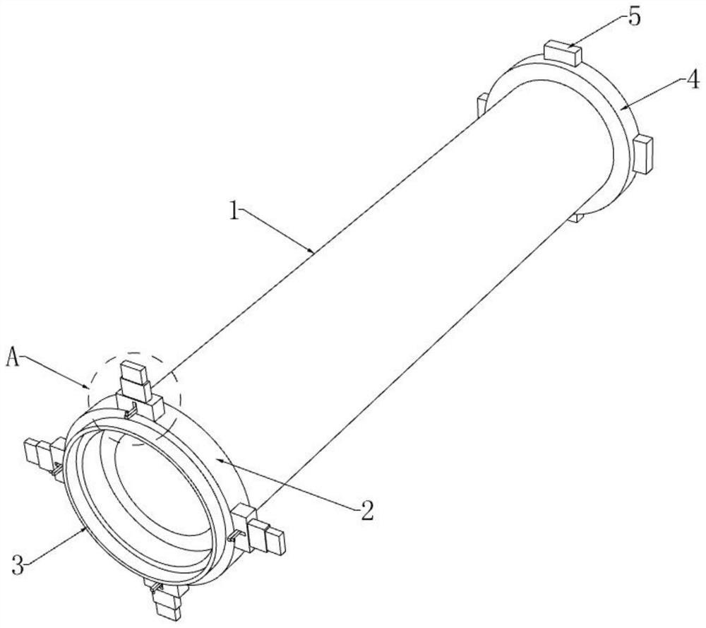
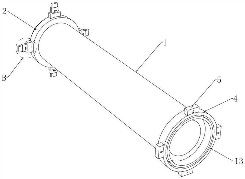
[0031] refer to figure 1 with image 3 , a plastic pipe connection structure used in water conservancy project construction, including a pipe 1, the two ends of the pipe 1 are respectively fixedly connected with a first connecting ring 2 and a second connecting ring 4, and the side of the first connecting ring 2 away from the pipe 1 The docking ring 3 is fixedly connected, and the side of the second connecting ring 4 far away from the pipeline 1 is provided with a ring-shaped docking groove 13 , and the docking ring 3 is matched with the docking groove 13 .
[0032] refer to Figure 1-3 , the circumferential side wall of the first connecting ring 2 is provided with four first fixed blocks 6 distributed in an annular array, and the circumferential side wall of the second connecting ring 4 is provided with four second fixed blocks 5 distributed in an annular array, and The first fixing block 6 and the second fixing block 5 are arranged correspondingly, and a dismounting mechan...
Embodiment 2
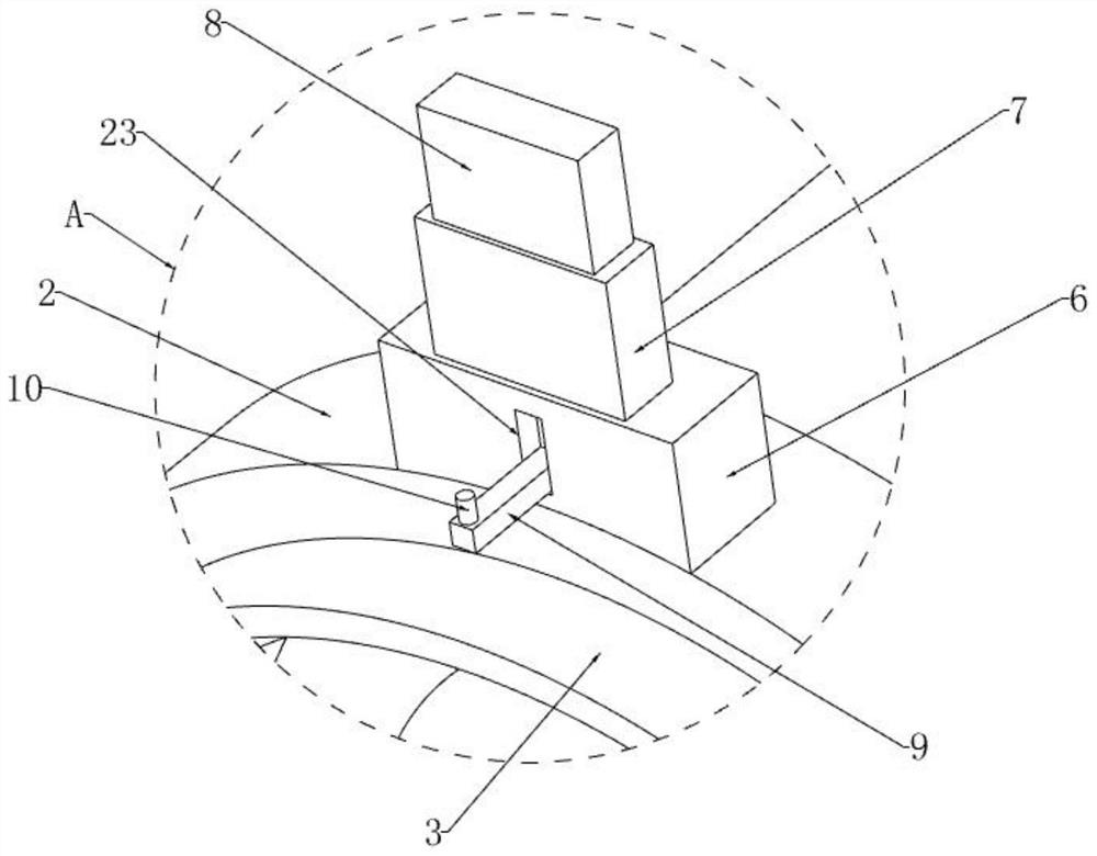
[0036] This embodiment adds a structure for driving the movable rod 21 on the basis of the first embodiment, so as to facilitate the operation of the movable rod 21, refer to figure 2 with Figure 6-9 , the top of the cover box 7 is open-shaped, and the inner wall of the cover box 7 is provided with a pressing block 8 through a damping sliding sleeve. The pressing block 8 is a hollow structure with an open bottom. There are driving blocks 24 distributed symmetrically in rotation, the bottom inner wall of the cover box 7 is fixedly connected with a fixed plate 22, and the movable rod 21 slides through the fixed plate 22 along the vertical direction, and the middle section of the movable rod 21 is provided with a slanted opening. Lifting groove, and the sliding in the lifting groove is provided with a lifting rod 19, the two ends of the lifting rod 19 are fixedly connected with the driven block 20 which is distributed symmetrically in rotation. The groove 25, the driving block...
Embodiment 3
[0039] This embodiment adds a limit mechanism on the basis of Embodiment 1 and Embodiment 2 to ensure the stability of the pressing block 8 and the sleeve 7, which not only improves the stability of the pipeline 1 when it is connected, refer to image 3 , Figure 4 with Figure 6-9 A second return spring 17 is fixedly connected between the end of the movable rod 21 away from the positioning plate 9 and the inner wall of the pressing block 8, and the side of the sleeve 7 close to the pipe 1 slides through and sets the limit rod 16, and the limit rod 16 is located at One end outside the cover box 7 is fixedly connected with a U-shaped pull bar 11, and the limit rod 16 is located on the outer circumferential side wall of the cover box 7 and is provided with a first back-moving spring 12, and the two ends of the first back-moving spring 12 are respectively connected to the sleeve. The side of the box 7 and the pull rod 11 close to each other is fixedly connected, and the rod body...
PUM
 Abstract
Description
Claims
Application Information
 - R&D
- Intellectual Property
- Life Sciences
- Materials
- Tech Scout
- Unparalleled Data Quality
- Higher Quality Content
- 60% Fewer Hallucinations
Browse by: Latest US Patents, China's latest patents, Technical Efficacy Thesaurus, Application Domain, Technology Topic, Popular Technical Reports.
© 2025 PatSnap. All rights reserved.Legal|Privacy policy|Modern Slavery Act Transparency Statement|Sitemap|About US| Contact US: help@patsnap.com