
Loading equipment for compound oil phase

A technology of loading equipment and compound oil phase, applied in the directions of container handles, external accessories, internal accessories, etc., can solve the problem that the collecting device cannot achieve the effect of blocking rainwater, and achieve the effect of convenient transportation

Pending Publication Date: 2022-05-13
FUZHOU GUOTAI COMPOSITE MATERIAL CO LTD
View PDF0 Cites 1 Cited by
  • Summary
  • Abstract
  • Description
  • Claims
  • Application Information

AI Technical Summary

Problems solved by technology

[0004] In order to overcome the shortcomings of existing collection devices that cannot achieve the effect of blocking rainwater, the technical problem to be solved is: to provide a loading device for composite oil phase that can achieve the effect of preventing rain

Method used


Image

  • Loading equipment for compound oil phase
  • Loading equipment for compound oil phase
  • Loading equipment for compound oil phase

Examples


Embodiment 1

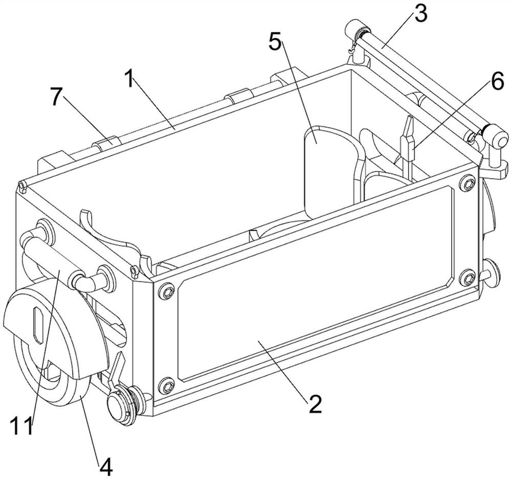
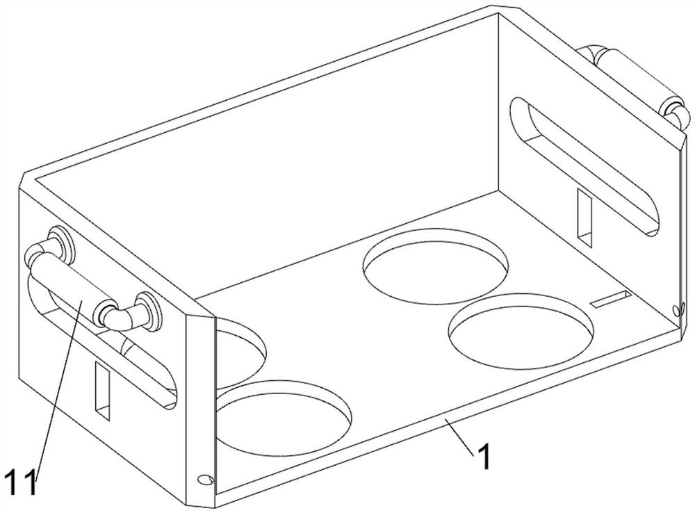
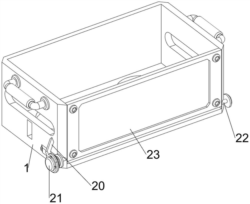
[0030] A loading device for complex oil phases such as Figure 1-2 As shown, it includes a loading box 1, a first handle 11, a blocking mechanism 2, and a cover mechanism 3. The left and right sides of the inner bottom wall of the loading box 1 are symmetrically opened with circular grooves front and rear, and the circular grooves of the loading box 1 are used to load compound oil. In contrast, the left and right sides of the loading box 1 are provided with first handles 11 through bolts, through the first handle 11, the loading box 1 is conveniently taken, and the loading box 1 is provided with a blocking mechanism 2, which is used to block the composite oil phase and load A cover mechanism 3 is provided above the box 1 for covering the top of the composite oil phase.

[0031] Such as image 3 As shown, the blocking mechanism 2 includes a support ring 20, a servo motor 21, a first rotating shaft 22 and an opening and closing plate 23. The front part of the lower left side of...

Embodiment 2

[0035] On the basis of Example 1, such as figure 1 and Figure 6As shown, a moving mechanism 4 is also included to facilitate the movement of the loading box 1. The moving mechanism 4 includes a first arc plate 40, a slide rail 41, a sliding plate 42, a first spring 43, a moving plate 44, a mounting rod 45 and Turning wheel 46, the left and right sides of opening and closing plate 23 rear bottoms are all provided with first arc-shaped plate 40 by bolt, and opening and closing plate 23 rotates and drives first arc-shaped plate 40 to rotate, and the left and right sides of loading box 1 inwall are all welded with Slide rail 41, slide rail 41 is all slidingly connected with moving plate 44, and moving plate 44 can move forward and backward on slide rail 41, and moving plate 44 inner side is all provided with sliding plate 42, and moving plate 44 and adjacent slide rail The first spring 43 is arranged between the 41 inner walls, under the action of the first spring 43, it can dri...


PUM


Abstract

The invention relates to loading equipment, in particular to loading equipment for a compound oil phase. The technical problem to be solved is to provide the loading equipment for the compound oil phase, which can realize a rainproof effect. According to the technical scheme, the loading equipment for the composite oil phase comprises a loading box, first handles, a blocking mechanism and a covering mechanism, the first handles are arranged on the left side and the right side of the loading box, the blocking mechanism is arranged on the loading box, and the covering mechanism is arranged above the loading box. The output shaft of the servo motor rotates to drive the first rotating shaft to rotate, the first rotating shaft rotates to drive the opening and closing plate to rotate, and the opening and closing plate can close or open the front side of the loading box.

Description

technical field [0001] The invention relates to a loading device, in particular to a loading device for composite oil phase. Background technique [0002] In the process of producing the composite oil phase, it is necessary to pack the composite oil phase in barrels. Generally, the composite oil phases are firstly packed in a collection cylinder, and then the collection cylinders filled with the composite oil phase are placed together. [0003] In the prior art, there are many pairs of loading tools, and the collection device is one of them. The collection cylinders filled with the composite oil phase are respectively placed in the collection device, and then people close the closing door of the collection device, so that the closing door can be closed. The collection tube is limited, but it does not have the effect of blocking rainwater. Now a loading device for composite oil phase that can achieve rainproof effect is developed. Contents of the invention [0004] In orde...

Claims


Application Information

Patent Timeline
Patent Type & Authority Applications(China)
IPC IPC(8): B65D25/04B65D25/10B65D25/28B65D25/20B65H75/44B65H75/40
CPCB65D25/04B65D25/10B65D25/28B65D25/20B65H75/44B65H75/40
Inventor 李宝林王小龙叶道源黄小林高晶
Owner FUZHOU GUOTAI COMPOSITE MATERIAL CO LTD
Learn More