
Vehicle stopping device for new energy vehicle

A technology of new energy vehicles and blocks, which is applied to vehicle components, transportation and packaging, and portable braking systems. Stable, wide range of effects

Pending Publication Date: 2022-05-13
王元文
View PDF0 Cites 0 Cited by
  • Summary
  • Abstract
  • Description
  • Claims
  • Application Information

AI Technical Summary

Problems solved by technology

[0003] Most of the existing car stop devices are relatively bulky and extremely inconvenient when transporting, which increases the work intensity of the staff. Although some car stop devices are equipped with moving wheels and electric suction cups to facilitate handling and fixing, when they are fixed, The adsorption of the electric suction cup will drive the device to move downward, which will increase the pressure on the moving wheel, which will easily cause damage to the moving wheel for a long time, reducing the service life of the device, or making the adsorption force of the electric suction cup insufficient, resulting in unreliable fixing of the device. Moreover, when the existing car blocking device needs to be transported multiple times to block automobile tires with different spacing and different sizes, it is time-consuming and laborious, and it is inconvenient to use. Therefore, this application discloses a car blocking device for new energy vehicles. devices to meet people's needs

Method used


Image

  • Vehicle stopping device for new energy vehicle
  • Vehicle stopping device for new energy vehicle
  • Vehicle stopping device for new energy vehicle

Examples


Embodiment

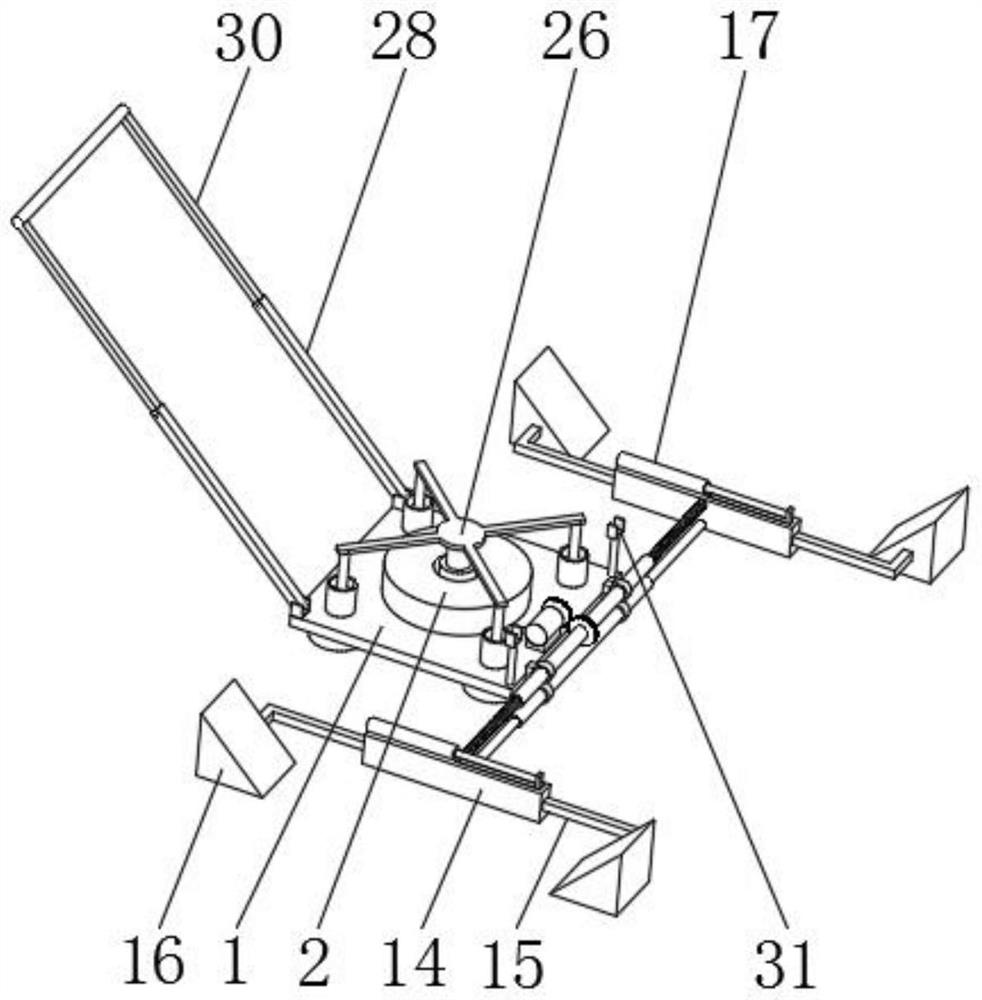
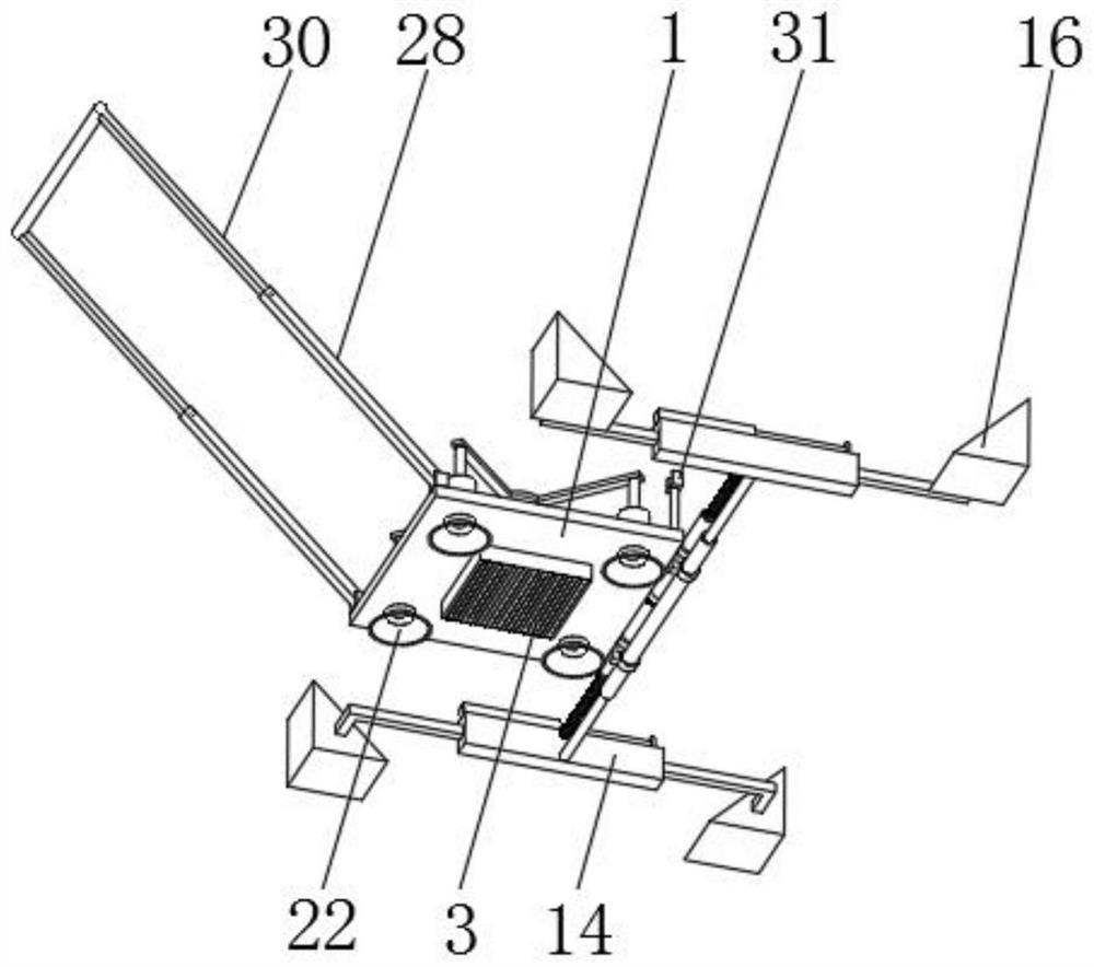
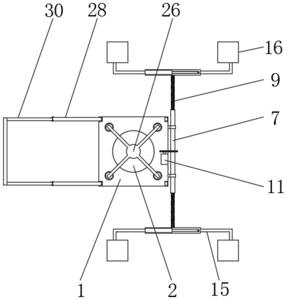
[0040] Example: Reference Figure 1-8 The shown car stop device for new energy vehicles includes a car stop base 1, four tape cartridge suction cups 22 are evenly socketed on the car stop base 1, and universal wheels 24 are arranged inside the four tape cartridge suction cups 22. The tape cartridge suction cup 22 and the universal wheel 24 are jointly connected with a switching assembly, and the switching assembly is used to adjust the adsorption force of the tape cartridge suction cup 22 and the position of the universal wheel 24, so that the device can be freely switched to a mobile or fixed state, and can be used in When fixed, the universal wheel 24 is protected. The side portion of the car stop base 1 is equipped with an adjustment assembly. Because of adjusting the lateral distance and the longitudinal distance between the four tire stoppers 16, automobile tires of different spacings and different sizes can be blocked.

[0041] With the above-mentioned structure, throug...


PUM


Abstract

The invention discloses a vehicle stopping device for a new energy vehicle, and relates to the field of new energy vehicles, the vehicle stopping device comprises a vehicle stopping base, four suction cups with barrels are uniformly mounted on the vehicle stopping base in a sleeving manner, universal wheels are arranged in the four suction cups with the barrels, the suction cups with the barrels and the universal wheels are jointly connected with a switching assembly, and the switching assembly is connected with the vehicle stopping base. And the switching assembly is used for adjusting the adsorption force of the sucker with the barrel and the position of the universal wheel. Through the arrangement of the switching assembly, the sucker with the barrel and the universal wheel, the adsorption force of the sucker with the barrel and the position of the universal wheel can be adjusted, so that the device can be freely switched to a movable or fixed state, the universal wheel can be protected during fixing, the service life of the device is prolonged, and through the arrangement of the adjusting assembly, the device is convenient to use. The transverse distance and the longitudinal distance of the tire stop blocks can be adjusted, so that the device can simultaneously stop automobile tires with different intervals and automobile tires with different sizes front and back, the application range is wide, and automobile stopping is more stable.

Description

technical field [0001] The invention relates to the field of new energy vehicles, in particular to a car stop device for new energy vehicles. Background technique [0002] New energy vehicles refer to vehicles that use unconventional vehicle fuels as power sources, integrate advanced technologies in vehicle power control and drive, and form vehicles with advanced technical principles, new technologies, and new structures. The power source of most existing new energy vehicles is a motor. After connecting the battery, electric control, and motor terminals with harnesses, they can be started directly, so that during installation, commissioning, and maintenance, due to factors such as accidentally turning on the power , the car may start without any precautions, and there is a great potential safety hazard. Therefore, it is necessary to use a car stop device to fix the new energy vehicle before inspection and maintenance. [0003] Most of the existing car stop devices are rela...

Claims


Application Information

Patent Timeline
Patent Type & Authority Applications(China)
IPC IPC(8): B60T3/00
CPCB60T3/00
Inventor 王元文
Owner 王元文
Learn More