Prepreg fiber yarn twisting prevention mechanism and using method thereof
A prepreg and fiber technology, applied in the field of anti-twisting devices, can solve the problems of easy twisting of fiber tows, and achieve the effects of ensuring uniformity, avoiding twisting, and easy control
- Summary
- Abstract
- Description
- Claims
- Application Information
AI Technical Summary
Problems solved by technology
Method used
Image

Examples
Embodiment 1
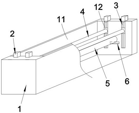
[0033] See Figure 1 , a prepreg fiber anti-screw mechanism, including box 1, drive assembly 2, lift assembly 3, guide rod 4 and fixing rod 5.
[0034] The top of the cabinet 1 is provided with an opening for the feed and outlet of the fiber tow 11. Drive assembly 2 is mounted at the top of one side wall of the enclosure 1. In the present embodiment, the drive component 2 is a motor 21, the drive end of the drive component 2 is the hinge of the motor 21, the motor 21 is mounted at the top of the right wall of the box 1, the hinge of the motor 21 is coaxially fixed to the top of the lifting assembly 3.
[0035] Lifting assembly 3 is installed in the box 1, the top of the lifting assembly 3 is connected to the drive end of the drive assembly 2. In the present embodiment, the lifting assembly 3 is a ball screw 31. Ball screw bearings can also be used for lifting assembly 3. The lifting end of the lifting assembly 3 is the nut of the ball screw 31, the nut of the ball screw 31 sli...
Embodiment 2
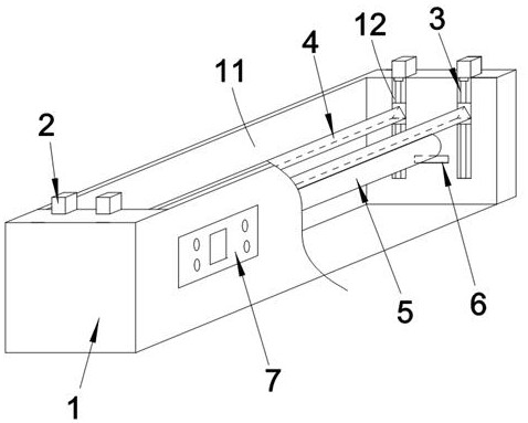
[0040] On the basis of Example 1, please refer to it together Figure 2 - Figure 4 , the difference of the present embodiment is:
[0041] Guide rod 4 has a circular arc angle of the edge, the edge parallel to the axis of the fixing rod 5, and the edge is used to form a sliding tension with the fiber tow. In the present embodiment, the guide rod 4 selects a triangular prism, the left and right ends of the triangular beam and the inner wall of the box 1 are sliding in conjunction, one or two prisms in the triangular prism can be used with the fiber tow in a sliding tension fit. The edge of the triangular prism is combined with the sliding of the fiber tow, so as to facilitate the formation of corners of the fiber tow, and the direction of movement of the fiber tow is adjusted, which not only avoids the screwing of the fiber tow in box 1, but also facilitates the adjustment of the length of the fiber tow in box 1.
[0042]At the same time, the motor 21 selects a servo motor 21. Plea...
Embodiment 3
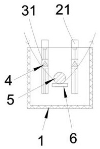
[0051] On the basis of Example 1, the difference of the present embodiment is:
[0052] The inner side wall of the cabinet 1 is provided with four chutes 12, the slots of the four chutes 12 are set in the height direction of the box 1, the four ball screws 31 are located in the four chutes 12, the nut slide of the ball screw 31 is mounted in the chute 12. Ball screw 31 slides in the chute 12, the chute 12 limits the nut of the ball screw 31, while also avoiding fibers wrapped around the ball screw 31, avoiding the occurrence of screws of the fibers.
[0053] At the same time, the guide rod 4 uses four prisms, and the left and right ends of the four prisms are sliding with the inner wall of the box 1. The four prisms can increase the sliding and cooperation with the fiber tow to form a corner, which is convenient for adjusting the direction of movement of the fiber tow multiple times, thereby further preventing the twisting of the fiber tow and achieving a flatter fiber during the ...
PUM
 Abstract
Description
Claims
Application Information
 - R&D
- Intellectual Property
- Life Sciences
- Materials
- Tech Scout
- Unparalleled Data Quality
- Higher Quality Content
- 60% Fewer Hallucinations
Browse by: Latest US Patents, China's latest patents, Technical Efficacy Thesaurus, Application Domain, Technology Topic, Popular Technical Reports.
© 2025 PatSnap. All rights reserved.Legal|Privacy policy|Modern Slavery Act Transparency Statement|Sitemap|About US| Contact US: help@patsnap.com