
Touch screen rear cover die-casting forming die with adjusting locking structure

A technology for forming molds and adjusting locks, which is used in forming tools, manufacturing tools, metal processing equipment, etc., can solve the problem that the mold falls on the ground, affects the overall mold matching and connectivity, and affects the installation accuracy of the stamping and forming back cover. Sex and other issues to achieve the effect of increasing the time spent

Pending Publication Date: 2022-05-13
徐州安彭电子科技有限公司
View PDF0 Cites 0 Cited by
  • Summary
  • Abstract
  • Description
  • Claims
  • Application Information

AI Technical Summary

Problems solved by technology

[0003] The purpose of the present invention is to address the shortcomings of the prior art, to provide a die-casting mold for the back cover of the touch screen with an adjustable locking structure, to solve the problem that the existing touch screen back cover proposed in the above background technology is all carried out by stamping equipment. One-time stamping and forming, but the existing stamping needs to replace different molds for stamping during the stamping process of the touch screen back cover of different lengths, which not only increases the time spent on mold replacement, but also easily causes the mold to fall on the ground during the mold replacement process As a result, it affects the compatibility and connectivity between the overall molds, which in turn affects the installation accuracy of the stamped back cover

Method used


Image

  • Touch screen rear cover die-casting forming die with adjusting locking structure
  • Touch screen rear cover die-casting forming die with adjusting locking structure
  • Touch screen rear cover die-casting forming die with adjusting locking structure

Examples


Embodiment Construction

[0039] The following will clearly and completely describe the technical solutions in the embodiments of the present invention with reference to the accompanying drawings in the embodiments of the present invention. Obviously, the described embodiments are only some, not all, embodiments of the present invention. Based on the embodiments of the present invention, all other embodiments obtained by persons of ordinary skill in the art without making creative efforts belong to the protection scope of the present invention.

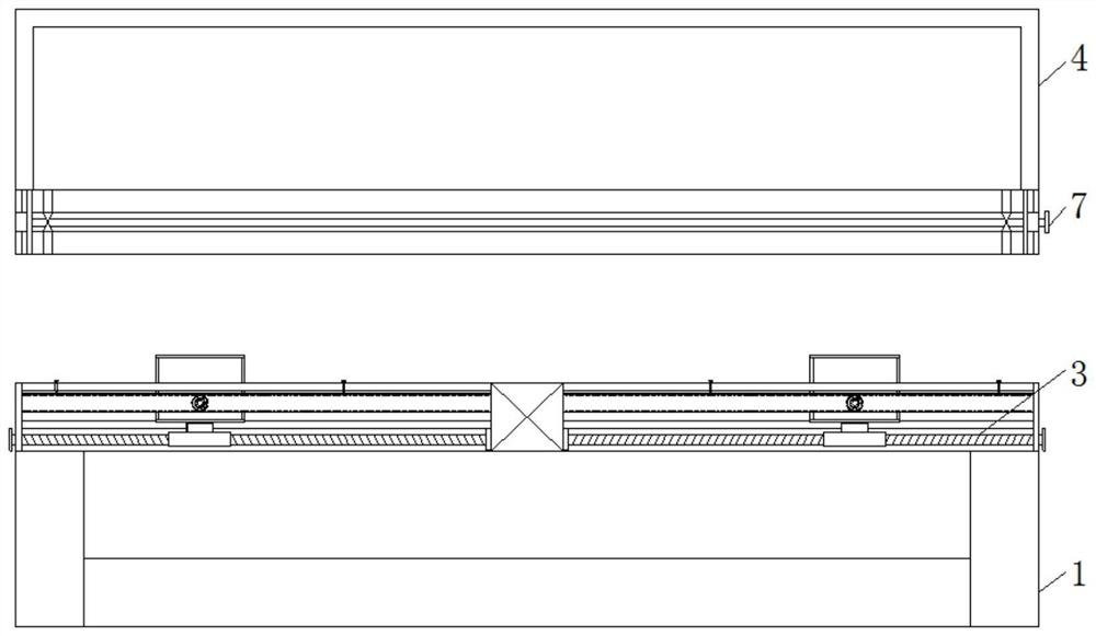
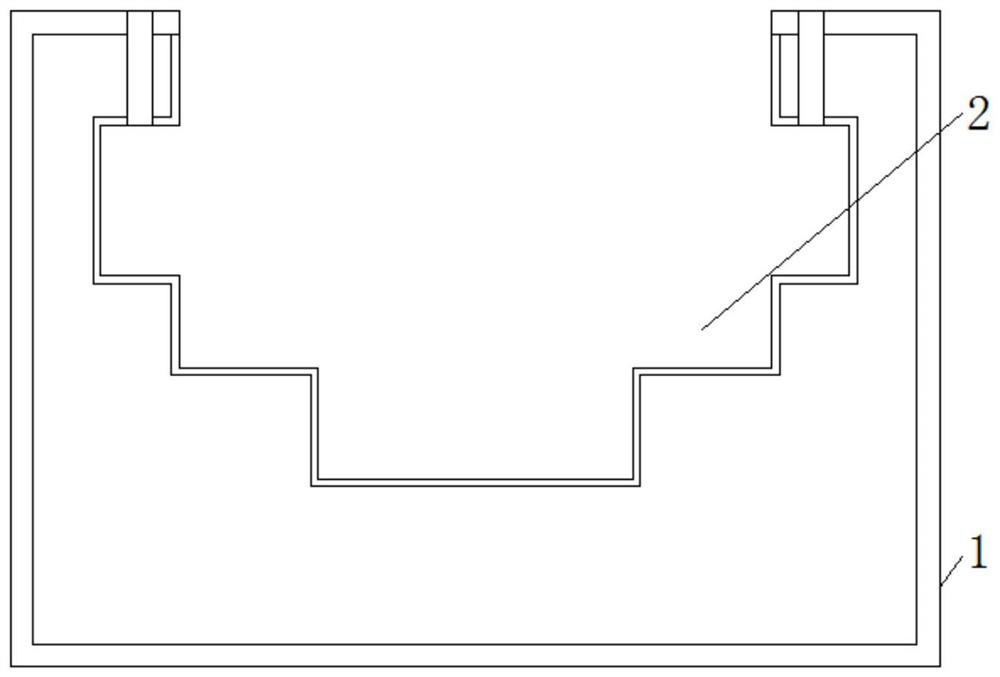
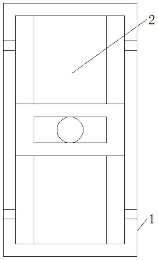
[0040] see Figure 1-9 , the present invention provides a technical solution: a touch screen rear cover die-casting mold with an adjustable locking structure, such as figure 1 , figure 2 , image 3 and Figure 4 As shown, the first chute 2 is provided on both sides above the bottom mold 1, and the installation groove is provided below the inside of the first chute 1, and the fixing grooves are provided on both sides of the first chute 2, and the top of the...


PUM


Abstract

The touch screen rear cover die-casting forming die with the adjusting and locking structure comprises a bottom die body, an adjusting and locking device, an upper die body, an adjusting device and a connecting plate, first sliding grooves are formed in the two sides of the upper portion of the bottom die body, fixing grooves are formed in the two sides of the interior of each first sliding groove, and a threaded connecting hole is formed in the upper portion of the bottom die body in a penetrating mode; a matching groove is formed in the middle of the upper portion of the bottom die, a movable groove is formed in the bottom of the upper die, second sliding grooves are formed in the two sides of the inner wall of the movable groove in a penetrating mode, through grooves are formed in the two sides of the upper die in a penetrating mode, a second connecting groove is formed in one side of the connecting plate, and the connecting plate is installed above the bottom die in the mode that a matching column penetrates through the matching groove. According to the touch screen rear cover die-casting forming die with the adjusting and locking structure, the first sliding groove is formed, the effect that connection is formed in the lower portion of the interior is achieved through the first sliding groove, and the effect that connection is formed in the two sides of the inner wall is achieved through the first sliding groove.

Description

technical field [0001] The invention relates to the technical field of touch screen back cover, in particular to a touch screen back cover die-casting mold with an adjustable locking structure. Background technique [0002] In the field of touch control, the touch function sheet of the film structure touch screen needs to be combined with two layers of conductive film materials to form a functional sheet, especially for film structure products above 10 inches, they are all combined with two layers of conductive film materials If the use of one layer of conductive film material can meet the needs of touch, there is no need to use the combination of two layers of film, which can reduce two layers of materials (one layer of conductive film material and one layer of optical film for bonding) Glue), the processing steps can also be reduced, no need to process two layers of materials and recombine, and at the same time, the product can be thinned and lightened. After the touch scr...

Claims


Application Information

Patent Timeline
Patent Type & Authority Applications(China)
IPC IPC(8): B21D22/02B21D37/04B21D37/12
CPCB21D22/02B21D37/12B21D37/04Y02P40/57
Inventor 张珞珞盛磊
Owner 徐州安彭电子科技有限公司
Learn More