Chair on bed for patient in intensive care unit

An intensive care unit and patient technology, applied in hospital beds, medical science, hospital equipment, etc., can solve problems such as high safety hazards, inconvenient transfer, skewed upper body parts, etc., to improve safety, complete functions, and improve stability. Effect

Inactive Publication Date: 2022-05-13
宣城市人民医院
View PDF0 Cites 1 Cited by
  • Summary
  • Abstract
  • Description
  • Claims
  • Application Information

AI Technical Summary

Problems solved by technology

[0003] In order to allow patients to sit and stand on the bed body of the existing intensive care unit, a bed board for the backrest that can be automatically lifted is added to the bed body, but the bed board for the backrest can only be lifted and lowered simply. Function, when the back and head of the critically ill patient are lifted, the upper body of the critically ill patient is prone to skewing in the left and right directions due to their weakness, which leads to a high potential safety hazard, and when the patient needs to be transferred, the transfer is also Not convenient enough

Method used


Image

  • Chair on bed for patient in intensive care unit
  • Chair on bed for patient in intensive care unit
  • Chair on bed for patient in intensive care unit

Examples


Embodiment 1

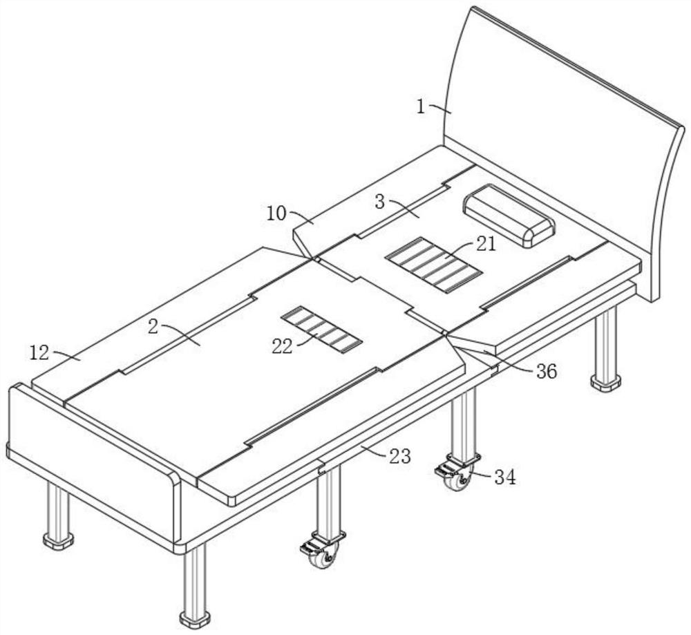
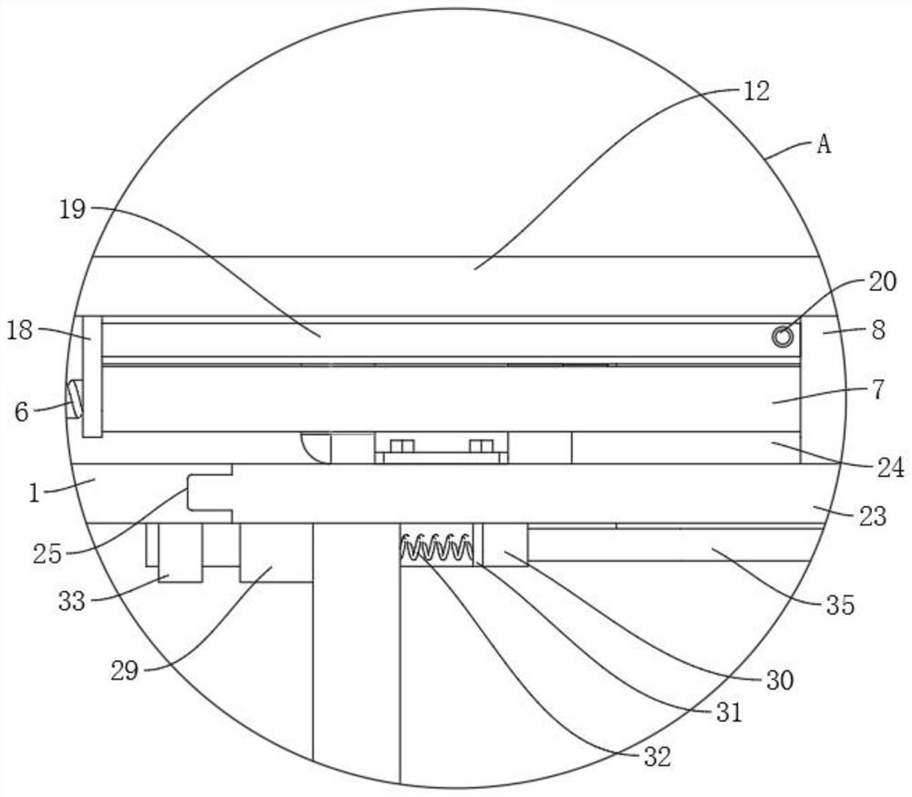
[0035] refer to Figure 1-10 , a bed seat for patients in an intensive care unit, including a bed body 1, and also includes: a horizontal plate 2 installed at the upper end of the bed end of the bed body 1, wherein the side wall of the horizontal plate 2 is connected with a backing plate 3 through a rotating shaft 4 for rotation, The backing board 3 is located at the upper end of the head of the bed body 1, and the bed body 1 is provided with a lifting assembly connected to the lower end of the backing board 3; Both sides, wherein, the first rotating rod 11 and the rotating shaft 4 are connected through the first interlocking mechanism; the slot 25 is arranged on the side wall of the bed body 1, wherein a slide plate 23 is slidably connected in the slot 25, and the slide plate 23 The upper end is provided with a rotating mechanism connected with the horizontal plate 2, the lower end of the slide plate 23 is equipped with a roller 34, and a self-locking assembly is provided bet...

Embodiment 2

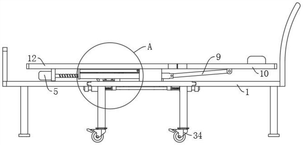
[0037] refer to Figure 1-3 as well as Figure 9, is basically the same as Embodiment 1, furthermore: the lifting assembly includes a first motor 5 fixedly installed on the lower end of the horizontal plate 2, the output end of the first motor 5 is fixedly installed with a threaded rod 6, and the outer wall of the threaded rod 6 is screwed There is an internally threaded pipe 7, the lower end of the horizontal plate 2 is fixedly connected with a sliding seat 8, the internally threaded pipe 7 is slidably connected to the sliding seat 8, and the end of the internally threaded pipe 7 is rotatably connected with a push rod 9, and the end of the push rod 9 is inclined upward It is arranged and rotated to be connected to the lower end of the first folding plate 10. When the patient needs to sit and stand, start the first motor 5, and the first motor 5 will drive the threaded rod 6 to rotate, and the threaded rod 6 will drive the inner threaded tube 7 to the bed. Sliding in the dire...

Embodiment 3

[0041] refer to figure 1 , Figure 4 as well as Figure 5 , which is basically the same as in Embodiment 1, furthermore: the first interlocking mechanism includes a first gear 14 fixedly installed at both ends of the rotating shaft 4, the rotating shaft 4 is fixedly connected with the horizontal plate 2, and one end of the two first rotating rods 11 is fixed The second gear 15 that is engaged with the first gear 14 is installed, and the first rotating rod 11 is fixedly connected with the first folding plate 10, and when the leaning plate 3 rotates upwards, the leaning plate 3 can rotate around the rotating shaft 4, thereby driving the two The second gear 15 on the first rotating rod 11 sweeps on the first gear 14, and the two second gears 15 will drive the two first rotating rods 11 to rotate, and the two first rotating rods 11 will drive the two first rotating rods 11. The first folded plate 10 is rotated upwards, and the two first folded plates 10 will block both sides of ...


PUM


Abstract

The invention discloses a bed seat for a patient in an intensive care unit, and belongs to the field of medical auxiliary equipment. The bed seat for the patient in the intensive care unit comprises a bed body and further comprises a horizontal plate, the horizontal plate is installed at the upper end of the bed tail of the bed body, the side wall of the horizontal plate is rotationally connected with a backup plate through a rotating shaft, the backup plate is located at the upper end of the bed head of the bed body, and a lifting assembly connected with the lower end of the backup plate is arranged on the bed body; the two first folding plates are rotationally connected to the two sides of the backup plate through first rotating rods, and the first rotating rods are connected with the rotating shafts through first interlocking mechanisms; the open groove is formed in the side wall of the bed body, a sliding plate is connected into the open groove in a sliding mode, and a rotating mechanism connected with the horizontal plate is arranged at the upper end of the sliding plate; according to the invention, a patient can be prevented from skewing when sitting, so that the safety is improved, and the patient can be conveniently moved, so that the bed body is more convenient to use and more complete in function.

Description

technical field [0001] The invention relates to the technical field of medical auxiliary equipment, in particular to a patient bed seat in an intensive care unit. Background technique [0002] Intensive care refers to intensive intensive treatment and nursing care for all kinds of critically ill patients admitted using various advanced medical technologies, modern monitoring and rescue equipment. To maximize the patient's survival and subsequent quality of life. [0003] In order to make the patient sit and stand on the bed body of the existing intensive care unit, a bed board for the backrest that can be automatically lifted is added to the bed body, but the bed board for the backrest can only be lifted and lowered simply. Function, when the back and head of the critically ill patient are lifted, the upper body of the critically ill patient is prone to skewing in the left and right directions due to their weakness, which leads to a high potential safety hazard, and when th...

Claims


Application Information

Patent Timeline
Patent Type & Authority Applications(China)
IPC IPC(8): A61G7/065A61G7/07A61G7/05
CPCA61G7/065A61G7/07A61G7/05
Inventor 吕梅叶
Owner 宣城市人民医院
Why Eureka
Try Eureka