
Emergency bandage cutting device for burn department

An emergency and bandage technology, applied in the field of cutters, can solve the problems of easy contamination of dust and impurities, affecting the efficiency of dressing progress, and inability to perform dressing work, and achieve the effect of improving work efficiency.

Active Publication Date: 2022-05-13
南京欣三人行网络科技有限公司
View PDF7 Cites 1 Cited by
  • Summary
  • Abstract
  • Description
  • Claims
  • Application Information

AI Technical Summary

Problems solved by technology

[0005] In order to overcome the existing bandage cutting equipment, there is no dust-proof cover, dust and impurities are easily contaminated on the bandage, and the bandage needs to be extended manually, which affects the progress and efficiency of the bandage and cannot perform better bandage work. The present invention The purpose is to provide an emergency dressing bandage cutter for burns department with dustproof function and automatic extension of gauze

Method used


Image

  • Emergency bandage cutting device for burn department
  • Emergency bandage cutting device for burn department
  • Emergency bandage cutting device for burn department

Examples


Embodiment 1

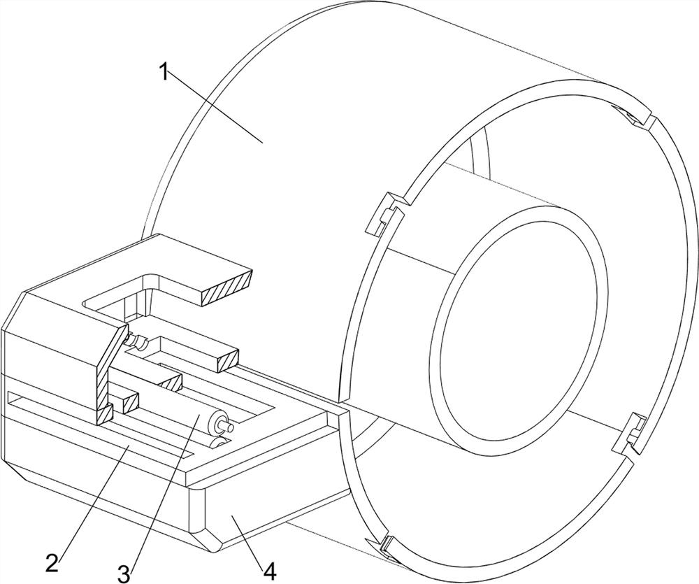
[0035] A kind of emergency dressing bandage cutter in burn department, such as Figure 1-Figure 8 As shown, it includes a placing frame 1, a supporting block 2, a roller 3, a first shell 4, a cutting assembly 5 and a closing assembly 6. The left side of the placing frame 1 is provided with a supporting block 2, and the left side of the supporting block 2 is symmetrically rotated up and down. Rollers 3 are provided, a first casing 4 is arranged between the upper and lower sides of the support block 2 and the placement frame 1, and the inside of the first casing 4 is provided with a cutting assembly 5, and the cutting assembly 5 is located inside the first casing 4, and the placement frame 1 The front side is provided with a closure assembly 6.

[0036] The cutting assembly 5 includes a pressing block 501, a first support rod 502, a first spring 503, a connecting rod 504 and a cutting knife 505. The first support rod 502 is symmetrically arranged on both sides of the front and b...

Embodiment 2

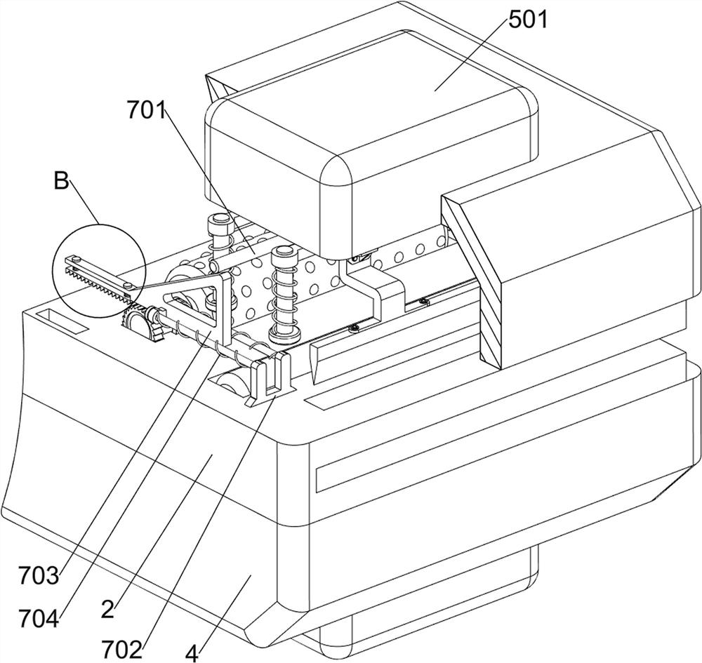
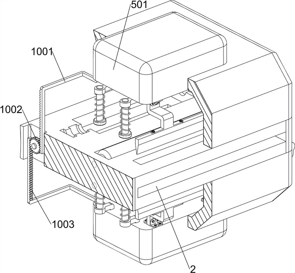
[0040] On the basis of Example 1, such as Figure 9-Figure 15 As shown, the extension assembly 7 is also included, and the extension assembly 7 includes a pressing rod 701, a support frame 702, a wedge block 703, a third spring 704, a ratchet bar 705, a fourth spring 706, a bearing 707, and a driving wheel 708 And ratchet 709, press bar 701 is all provided with pressing bar 701 in the middle of pressing block 501, support frame 702 is all symmetrically provided with front and back both sides up and down of support block 2, all sliding type is provided with wedge-shaped block 703 on support frame 702, wedge-shaped block 703 is all with pressing Rod 701 cooperates, and the third spring 704 is arranged symmetrically between the wedge block 703 and the support frame 702, and the third spring 704 is all sleeved on the support frame 702, and the right side of the wedge block 703 is provided with a ratchet bar 705 slidingly. A fourth spring 706 is symmetrically arranged between the r...


PUM


Abstract

The invention relates to a cutting device, in particular to an emergency bandage cutting device for the burn department. The invention aims to provide the emergency bandage cutting device for the burn department, which has a dustproof effect and can automatically extend gauze. The emergency bandage cutting device for the burn department comprises a containing frame and a supporting block, and the supporting block is arranged on one side of the containing frame; the rollers are rotationally arranged on one side of the interior of the supporting block in an up-down symmetrical mode; the first shells are arranged between the upper side and the lower side of the supporting block and the placing frame; the cutting assemblies are arranged on the inner side of the first shell, and the cutting assemblies are located on the inner side of the first shell. The wedge-shaped block and the ratchet bar move rightwards to reset, at the moment, the ratchet bar is meshed with the ratchet wheel rightwards, then the ratchet wheel and the driving wheel are driven to rotate, the bandage is stretched out leftwards under the action of rotation of the driving wheel, and the operation is repeated, so that people can conveniently bind a patient, and the effect of automatically extending the bandage is achieved.

Description

technical field [0001] The invention relates to a cutter, in particular to a bandage cutter for emergency use in the department of burns. Background technique [0002] The burn department is a department that provides corresponding nursing and treatment according to the degree of burns of patients, and bandages are gauze bandages wrapped around the injured parts of patients, which have the characteristics of reducing pain, swelling and increasing fixation of the injured parts. [0003] After a patient has a large area of ​​burns, the amount of bandages required is large, and the medical staff need to treat and bandage the injured area of ​​the patient. In the existing dressing bandage cutting equipment, there is no dust-proof cover, and dust and impurities in the air are easy to burn. Contaminated on the bandage, if the patient is bandaged and the patient's wound is infected, the bandage needs to be extended manually, which affects the progress and efficiency of the bandage,...

Claims


Application Information

Patent Timeline
Patent Type & Authority Applications(China)
IPC IPC(8): A61F15/02A61F15/00
CPCA61F15/02A61F15/007Y02A50/30
Inventor 林文
Owner 南京欣三人行网络科技有限公司
Learn More