Sacroiliac joint fusion cage, holding device thereof and implantation channel setting tool of sacroiliac joint fusion cage

A technology of sacroiliac joints and fusion devices, applied in joint implants, joint implants, medical science, etc. The effect of less number of objects and simple operation steps

Pending Publication Date: 2022-05-13
SHANGHAI SANYOU MEDICAL CO LTD
View PDF0 Cites 0 Cited by
  • Summary
  • Abstract
  • Description
  • Claims
  • Application Information

AI Technical Summary

Problems solved by technology

[0003] 1) 2-3 fusion devices of different sizes are arranged at certain intervals and implanted in the sacroiliac joint area, so as to achieve the effect of stabilizing the joint through the combination of fusion devices; this type of fusion device adopts a rotary structure and comes with external threads , the externally threaded screws that come with this type of fusion device are drilled into the articular bone tissue; this type of solution has the disadvantages of a large number of implants, relatively accurate positioning of each fusion device, and complicated implantation operations;
[0004] 2) A single fusion device is implanted in the joint space between the sacrum and ilium, and then several screws are used to connect the sacrum and ilium to stabilize the joint area; the shape of this type of fusion device is non-rotating similar to the thoracolumbar fusion device This type of scheme has disadvantages such as a large number of implants, complicated approach positioning, and many surgical steps;

Method used


Image

  • Sacroiliac joint fusion cage, holding device thereof and implantation channel setting tool of sacroiliac joint fusion cage
  • Sacroiliac joint fusion cage, holding device thereof and implantation channel setting tool of sacroiliac joint fusion cage
  • Sacroiliac joint fusion cage, holding device thereof and implantation channel setting tool of sacroiliac joint fusion cage

Examples


Embodiment Construction

[0088] The implementation of the present invention will be illustrated by specific specific examples below, and those skilled in the art can easily understand other advantages and effects of the present invention from the contents disclosed in this specification.

[0089] Please refer to attached picture. It should be noted that the structures, proportions, sizes, etc. shown in the drawings attached to this specification are only used to match the content disclosed in the specification, for those who are familiar with this technology to understand and read, and are not used to limit the implementation of the present invention. Limiting conditions, so there is no technical substantive meaning, any modification of structure, change of proportional relationship or adjustment of size, without affecting the effect and purpose of the present invention, should still fall within the scope of the present invention. The disclosed technical content must be within the scope covered. At t...


PUM


Abstract

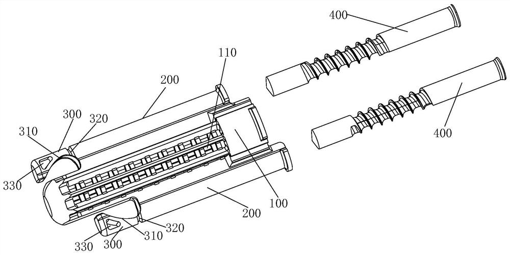
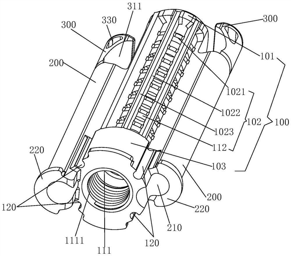
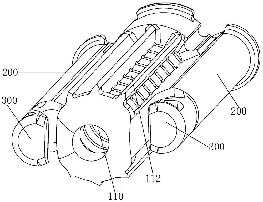
The invention provides a sacroiliac joint fusion cage, a holding device of the sacroiliac joint fusion cage and an implantation channel setting tool of the sacroiliac joint fusion cage. The fusion cage body comprises a bone grafting cylinder and two anti-torsion cylinders; a bone grafting cavity is formed in the bone grafting cylinder, a plurality of bone grafting holes are formed in the outer side surface of the bone grafting cylinder, and each bone grafting hole is communicated with the bone grafting cavity; the two anti-torsion cylinders are oppositely arranged on the outer side face of the bone grafting cylinder, and each anti-torsion cylinder is provided with an axial channel; the front end of each anti-torsion cylinder is provided with an opening head; a notch part is arranged on the outer side surface of each expanding head and faces the bone grafting cylinder; the notch part extends to the rear end of the opening head; a sunken groove is formed in the outer side face of each expanding head in the circumferential direction of the outer side face of the expanding head, and the sunken grooves are located in the connecting positions of the expanding heads and the anti-torque cylinder; each screw is used for penetrating into the corresponding axial channel. According to the sacroiliac joint fusion cage, the number of implants is small, and the surgical operation steps are simple.

Description

technical field [0001] The invention relates to the technical field of medical instruments for orthopedic surgery, in particular to a sacroiliac joint fusion device, its holder and its implantation channel setting tool. Background technique [0002] Surgical treatment of degenerative sacroiliitis and sacroiliac joint disorders usually uses joint fusion to stabilize the joints, eliminate pain, and restore the function of the sacroiliac joints. Currently, sacroiliac joint fusion options can be divided into two categories: [0003] 1) 2-3 fusion devices of different sizes are arranged at certain intervals and implanted in the sacroiliac joint area, so as to achieve the effect of stabilizing the joint through the combination of fusion devices; this type of fusion device adopts a rotary structure and comes with external threads , the externally threaded screws that come with this type of fusion device are drilled into the articular bone tissue; this type of solution has the disa...

Claims


Application Information

Patent Timeline
Patent Type & Authority Applications(China)
IPC IPC(8): A61F2/30A61F2/46
CPCA61F2/30988A61F2/30734A61F2/30749A61F2/4603A61F2002/30995A61F2002/30754
Inventor 周跃李长青刘明岩方尚庆让查尔斯·勒约艾克郑文杰张涛黄渤潘勇
Owner SHANGHAI SANYOU MEDICAL CO LTD
Why Eureka
Try Eureka