Limiting device for lowest down-regulation position of header of agricultural harvester
A limit device and harvester technology, applied in the agricultural field, can solve the problems of header blade damage, header blockage, increase the cost of replacing blades and labor, etc., to save cost and labor, reduce pushing resistance, and improve work efficiency. Effect
- Summary
- Abstract
- Description
- Claims
- Application Information
AI Technical Summary
Problems solved by technology
Method used
Image
Examples
Embodiment 1
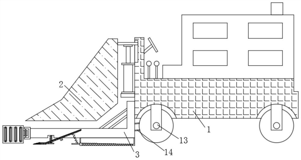
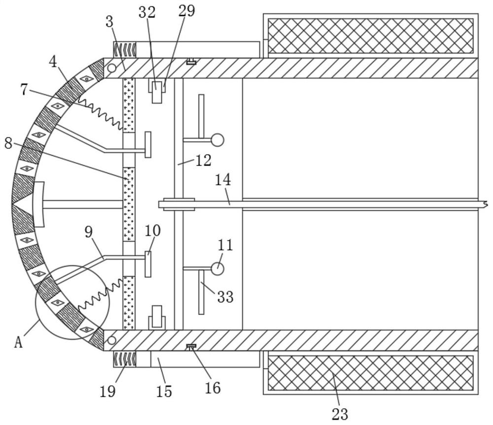
[0038] refer to Figure 1-10 , a limit device for the lowest lowering position of the agricultural harvester header, comprising an agricultural harvester body 1, a header body 2 is slidably installed on the left end of the agricultural harvester body 1, and a limit plate 3 is provided on the lower side of the header body 2 , the right end of the limiting plate 3 is fixedly installed on the agricultural harvester body 1, the left end of the limiting plate 3 is hinged with arc-shaped push plates 4 on the front and rear sides, and the arc-shaped push plate 4 is provided with a plurality of openings 5. The openings 5 are arranged at equal intervals, and four openings 5 are arranged symmetrically in front and back respectively. Limiting strips 6 are arranged inside the openings 5, and the shape of the limiting strips 6 is arranged in a rhombus shape. Both ends are fixedly equipped with circular rods, and the upper and lower ends of the opening 5 are provided with circular groov...
Embodiment 2
[0041] refer to Figure 1-10 , in this embodiment, it is basically the same as Embodiment 1, and more optimally, the front and rear sides of the limiting plate 3 are provided with loading and unloading plates 15, and the front and rear ends of the limiting plate 3 correspond to the middle of the loading and unloading plates 15. A turning slot 16 is opened, and the loading and unloading plate 15 is rotated to connect with the limiting plate 3. The upper end of the loading and unloading plate 15 is provided with a limiting groove 17, and the inner bottom of the loading and unloading plate 15 is provided with a number of filter strips 18, which are equally spaced between the filter strips. The left end of the loading and unloading plate 15 is fixedly equipped with a shovel head plate 19, the shape of the loading and unloading plate 15 is “J” shape, the shape of the shovel head plate 19 is triangular, and the lower right side of the loading and unloading plate 15 is provided with a...
Embodiment 3
[0044] refer to Figure 1-10 , in this embodiment, it is basically the same as Embodiment 1, and more optimally, the upper end of the shovel head plate 19 is provided with several barb strips 20, and the lower end of the barb strip 20 is fixedly connected with a barb plate 21, and the barb strip 20 And the barb plate 21 all runs through the shovel head plate 19 upper end, and the lower end of the barb plate 21 is fixedly equipped with some springs 22, and the lower end of the spring two 22 is fixedly connected to the shovel head plate 19 inside;
[0045] During use, some barb strips 20 that are set are convenient to play a position-limiting effect on the stone, reducing the possibility that the stone will slide off from the shovel head plate 19, and the barb plate 21 and the spring 22 that are provided are convenient to move according to the position of the stone. The height of the self-adaptive adjustment barb plate 21 on the shovel head plate 19 has wide practicability.
[...
PUM
 Abstract
Description
Claims
Application Information
 - R&D
- Intellectual Property
- Life Sciences
- Materials
- Tech Scout
- Unparalleled Data Quality
- Higher Quality Content
- 60% Fewer Hallucinations
Browse by: Latest US Patents, China's latest patents, Technical Efficacy Thesaurus, Application Domain, Technology Topic, Popular Technical Reports.
© 2025 PatSnap. All rights reserved.Legal|Privacy policy|Modern Slavery Act Transparency Statement|Sitemap|About US| Contact US: help@patsnap.com


