
Electronic expansion valve

A technology of electronic expansion valve and valve needle, which is applied in the direction of lift valve, valve details, valve device, etc., can solve the problems of complex structure of rotor components, and achieve the effect of simplifying structure and reducing volume

Pending Publication Date: 2022-05-10
DUNAN ENVIRONMENT TECH
View PDF10 Cites 0 Cited by
  • Summary
  • Abstract
  • Description
  • Claims
  • Application Information

AI Technical Summary

Problems solved by technology

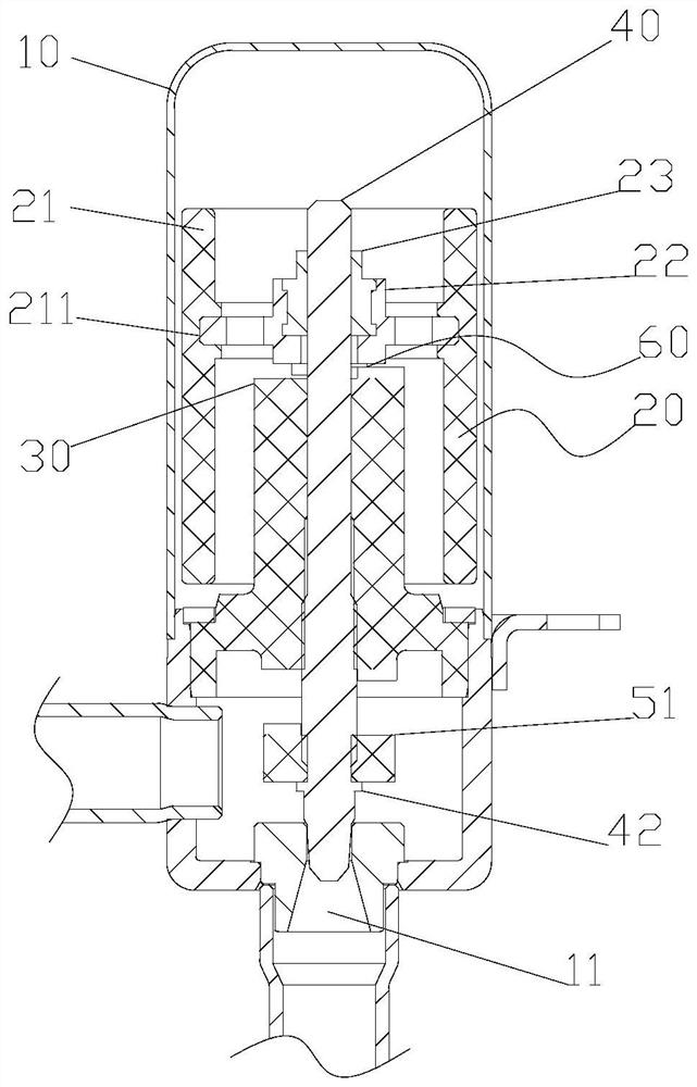
[0005] The invention provides an electronic expansion valve to solve the problem of complex structure of the rotor assembly in the prior art

Method used


Image

  • Electronic expansion valve
  • Electronic expansion valve
  • Electronic expansion valve

Examples


Embodiment Construction

[0032] The following will clearly and completely describe the technical solutions in the embodiments of the present invention with reference to the accompanying drawings in the embodiments of the present invention. Obviously, the described embodiments are only some, not all, embodiments of the present invention. The following description of at least one exemplary embodiment is merely illustrative in nature and in no way taken as limiting the invention, its application or uses. Based on the embodiments of the present invention, all other embodiments obtained by persons of ordinary skill in the art without creative efforts fall within the protection scope of the present invention.

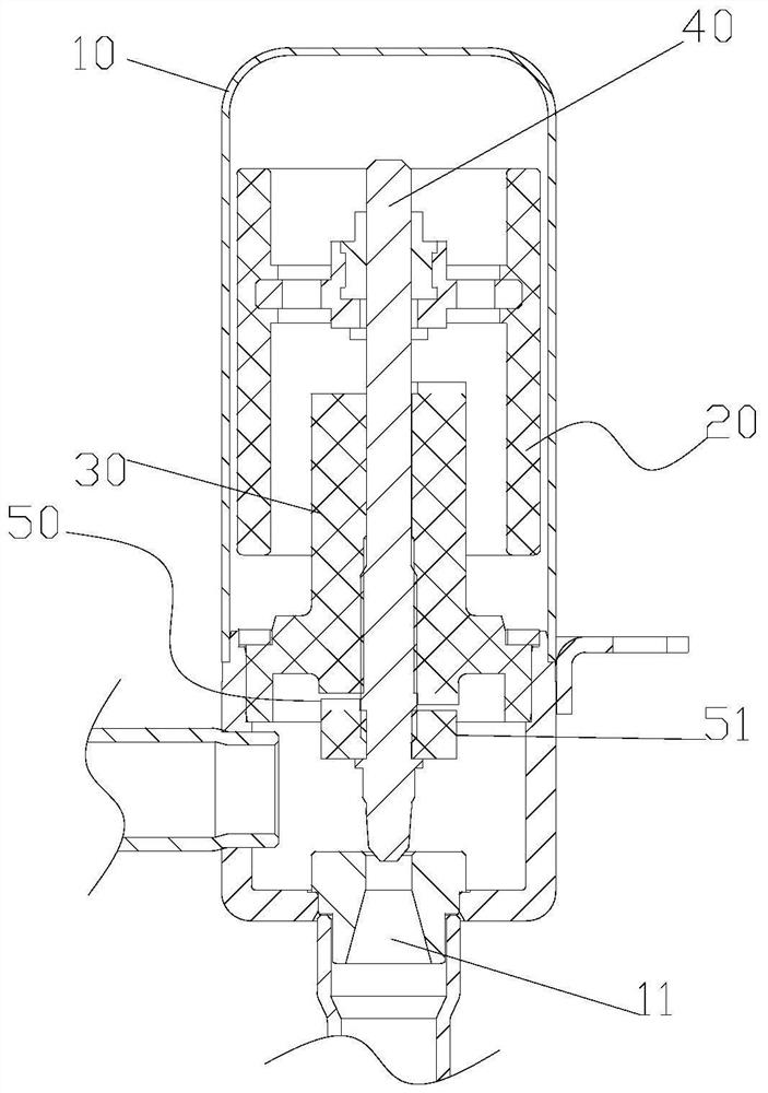
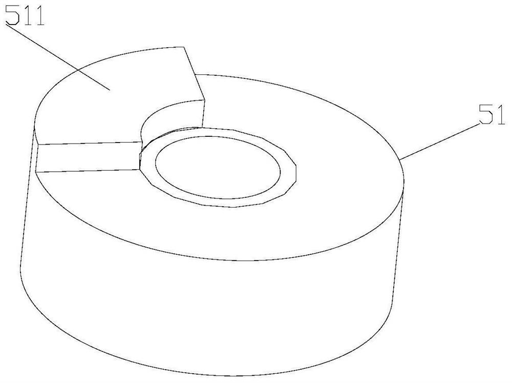
[0033] Such as figure 1 and figure 2 As shown, the embodiment of the present invention provides an electronic expansion valve, which includes a housing 10 , a rotor assembly 20 , a nut seat 30 , a valve needle 40 and an upper stop structure 50 . Wherein, the housing 10 has a valve port 11 , and th...


PUM


Abstract

The invention provides an electronic expansion valve which comprises a shell provided with a valve port, a valve element and a valve element. The rotor assembly is rotatably arranged in the shell; the nut seat is arranged in the shell, and the lower end of the nut seat is close to the valve port; the valve needle penetrates through the nut seat and is in threaded connection with the nut seat, and the rotor assembly is in driving connection with the valve needle so as to drive the valve needle to rotate relative to the nut seat; the upper stop structure is fixedly arranged at the end, close to the valve port, of the valve needle and located between the nut seat and the valve port so as to limit the maximum distance between the valve needle and the valve port. Through the technical scheme provided by the invention, the problem of complex structure of the rotor assembly in the prior art can be solved.

Description

technical field [0001] The present invention relates to the technical field of electronic expansion valves, in particular to an electronic expansion valve. Background technique [0002] At present, the electronic expansion valve includes a housing, a rotor assembly, a nut seat, a screw, and a valve needle. The rotor assembly is rotatably arranged in the housing, the nut seat is fixedly arranged in the housing, and the screw rod is threaded in the nut seat and threaded with the nut seat. Cooperate, the rotor assembly is connected with the screw drive, and the screw is connected with the valve needle drive. Driven by the rotor assembly, the screw rod can be used to drive the valve needle to move relative to the valve port on the casing, thereby realizing on-off valve operation. [0003] In order to limit the minimum distance and the maximum distance of the valve needle relative to the valve port, an upper stop structure and a lower stop structure are arranged on the upper end...

Claims


Application Information

Patent Timeline
Patent Type & Authority Applications(China)
IPC IPC(8): F16K1/02F16K1/32F16K1/36F16K1/50F16K31/08F25B41/34
CPCF16K1/02F16K1/32F16K1/36F16K1/50F16K31/08Y02B30/70
Inventor 曾庆军陈勇好
Owner DUNAN ENVIRONMENT TECH
Learn More