Wet dust collector

A wet dust collector and area technology, applied in the field of dust removal device and wet dust collector, can solve the problems of short service life of water pump, high use cost of wet dust collector, easy damage of water pump, etc., to save electric energy and improve water mist generation. Quantity and the effect of reducing manufacturing costs

Pending Publication Date: 2022-05-10
安徽正义研磨环保科技有限公司
View PDF8 Cites 0 Cited by
  • Summary
  • Abstract
  • Description
  • Claims
  • Application Information

AI Technical Summary

Problems solved by technology

The spraying device of the existing wet dust collector needs to use the water pump to supply water for spraying. As the dust removal time increases, the washing liquid becomes more and more dirty, causing the water pump to be easily damaged
In order to solve the above technical problems, those skilled in the art usually choose water pumps with excellent quality. Although the maintenance cycle of water pumps can be extended, there is still the problem that the service life of water pumps is much shorter than that of other components, so there is a use cost for wet dust collectors. Problems such as high and poor stability

Method used


Image

  • Wet dust collector
  • Wet dust collector

Examples


Embodiment 1

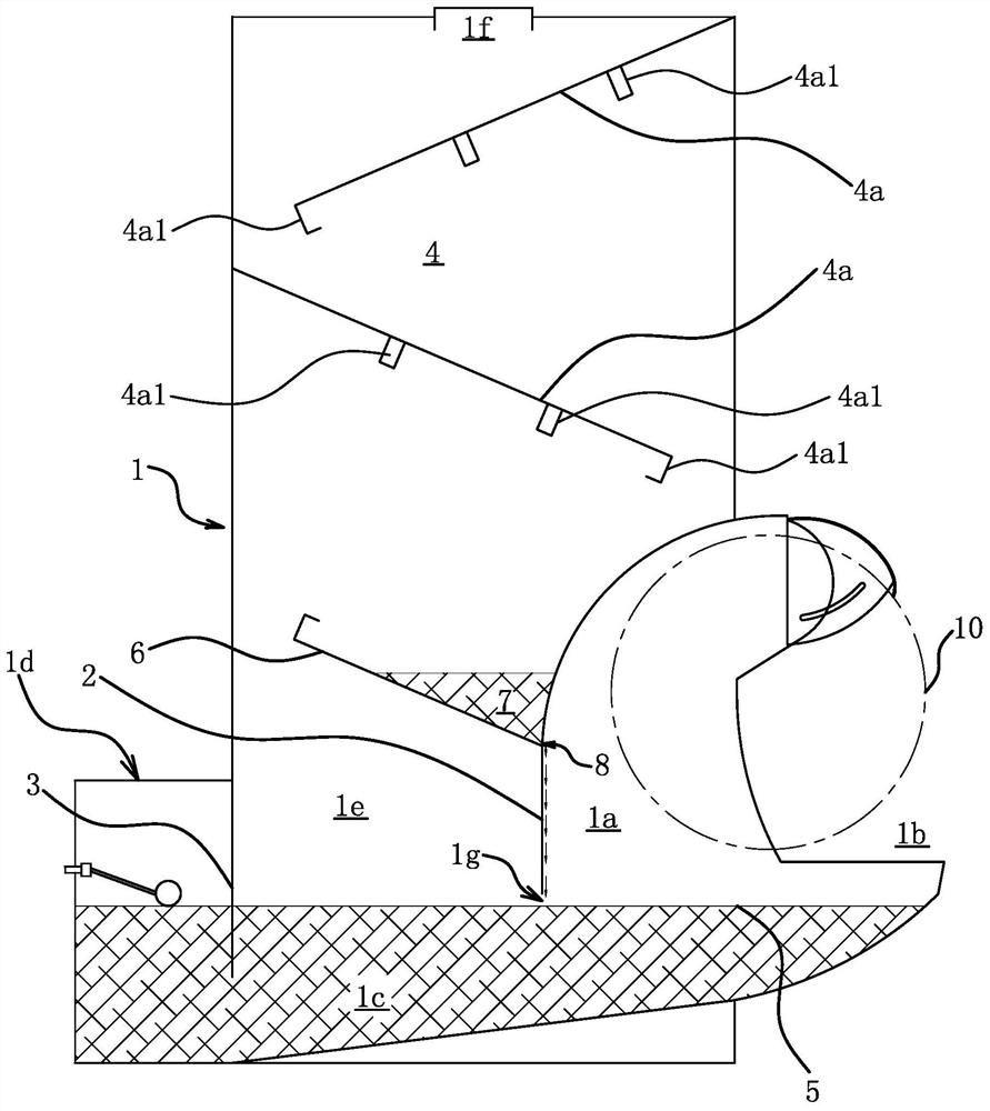
[0026] Embodiment one: if figure 1 As shown, the wet dust collector includes a housing 1 with an inner cavity. The front part of the inner cavity in the housing 1 is a dust inlet area 1a; a manipulation port 1b is opened on the front side wall of the dust inlet area 1a. The bottom of the inner cavity is the water holding area 1c, that is, the dust inlet area 1a is located above the front part of the water holding area 1c.

[0027] The rear part of the inner cavity is the air outlet area 1e, and the dust inlet area 1a and the air outlet area 1e are separated by a partition 2 fixedly connected with the housing 1, and the bottom of the partition 2 is vertically arranged. An air outlet 1f is opened on the top surface of the air outlet area 1e in the casing 1 . According to actual conditions, the air outlet 1f can be connected to the fan through a pipe, or the fan connected to the air outlet 1f can be directly fixed on the top plate of the housing 1 .

[0028] A medium separatio...

Embodiment 2

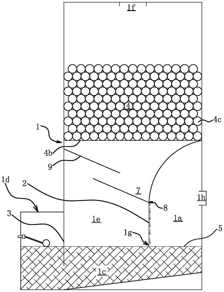
[0034] Embodiment 2: The structure and principle of this embodiment are basically the same as those of Embodiment 1. The basic similarities will not be described redundantly, and only the differences will be described. The differences are as follows: figure 2 As shown, the front side wall of the dust inlet area 1a is not provided with a control port 1b, but with an air inlet port 1h.

[0035] The medium separation structure 4 includes a bearing net 4b arranged in the middle of the air outlet area 1e, the bearing net 4b is connected to the housing 1, and a large number of hollow multi-faceted plastic balls 4c are filled in the air outlet area 1e; that is, the hollow multi-faceted plastic balls 4c are stacked On the carrying net 4b, a large number of multi-faceted plastic balls stacked together also have the effect of separating water mist and dust, and the number of multi-faced plastic balls can be flexibly adjusted according to the actual water mist and dust separation effect,...

Embodiment 3

[0037] Embodiment 3: The structure and principle of this embodiment are basically the same as that of Embodiment 1. The basic similarities are no longer redundantly described, and only the differences are described. The difference is that there is a drain on the bottom plate of the water storage tank 7 8. In this way, the washing liquid will flow downward along the surface of the partition plate 2 on the side of the air outlet area 1e, thereby forming a water curtain at the air passage gap 1g.


PUM

PropertyMeasurementUnit
dust removal efficiencyaaaaaaaaaa

Abstract

The invention provides a wet dust collector, and belongs to the technical field of operation. The wet dust collector solves the problem that the moisture content of airflow in an existing wet dust collector is insufficient. The wet dust collector comprises a shell with an inner cavity, the inner cavity of the shell is provided with a water containing area, a dust inlet area and an air outlet area, the water containing area is located at the bottom of the inner cavity of the shell, the dust inlet area and the air outlet area are located above the water containing area, the dust inlet area and the air outlet area are separated through a partition plate, and the partition plate is fixedly connected with the shell; when the washing liquid is contained in the water containing area, an air passing gap is reserved between the bottom edge of the partition plate and the liquid level of the washing liquid; a medium separation structure is arranged in the air outlet area, and washing liquid separated by the medium separation structure can flow downwards along the side face of the partition plate and flow to the air passing gap. Under the action of the high-speed air flow, the flowing washing liquid is crushed into water drops and water mist, so that the content of the water drops and the water mist in the air flow is increased, and the water drops and the water mist can be fully mixed with dust.

Description

[0001] This application is a divisional application of invention name: wet dust collector, application number: 201710211613.3, filing date: 2017.04.01. technical field [0002] The invention belongs to the technical field of operations, and relates to a dust removal device, in particular to a wet dust collector. Background technique [0003] Wet dedusting is a method of cleaning the gas by fully contacting the cleaning liquid (usually water) with the dusty gas to wash down the dust particles. The wet dust removal efficiency is high, the wet dust collector has a simple structure, low cost, small footprint, convenient operation and maintenance, and is especially suitable for dealing with high temperature, high humidity, flammable and explosive dusty gases. [0004] When the induced draft fan is started, the air in the dust collector is quickly discharged, and at the same time, the dusty gas enters the interior of the dust collector along the flue under the action of atmospheri...

Claims


Application Information

Patent Timeline
Patent Type & Authority Applications(China)
IPC IPC(8): B01D50/40B01D50/10B01D47/00
CPCB01D47/00
Inventor 陈美青
Owner 安徽正义研磨环保科技有限公司
Why Eureka
Try Eureka