
Surgical navigation system for wound surface and dermatological microparticle skin detection and drilling

A dermatology and microskin technology, applied in the field of surgical navigation systems, can solve the problems of poor general condition and difficult wound repair, and achieve the effect of distance

Pending Publication Date: 2022-05-10
C&A LIGHT INT MEDICAL INVESTMENT MANAGEMENT BEIJING CO LTD
View PDF5 Cites 0 Cited by
  • Summary
  • Abstract
  • Description
  • Claims
  • Application Information

AI Technical Summary

Problems solved by technology

These patients are either old and frail, or combined with multiple chronic diseases, and their general condition is poor. It is difficult to repair wounds, which brings a heavy burden to patients, families and society.

Method used


Image

  • Surgical navigation system for wound surface and dermatological microparticle skin detection and drilling
  • Surgical navigation system for wound surface and dermatological microparticle skin detection and drilling
  • Surgical navigation system for wound surface and dermatological microparticle skin detection and drilling

Examples


Embodiment 1

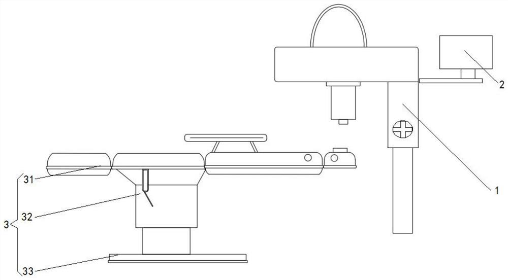
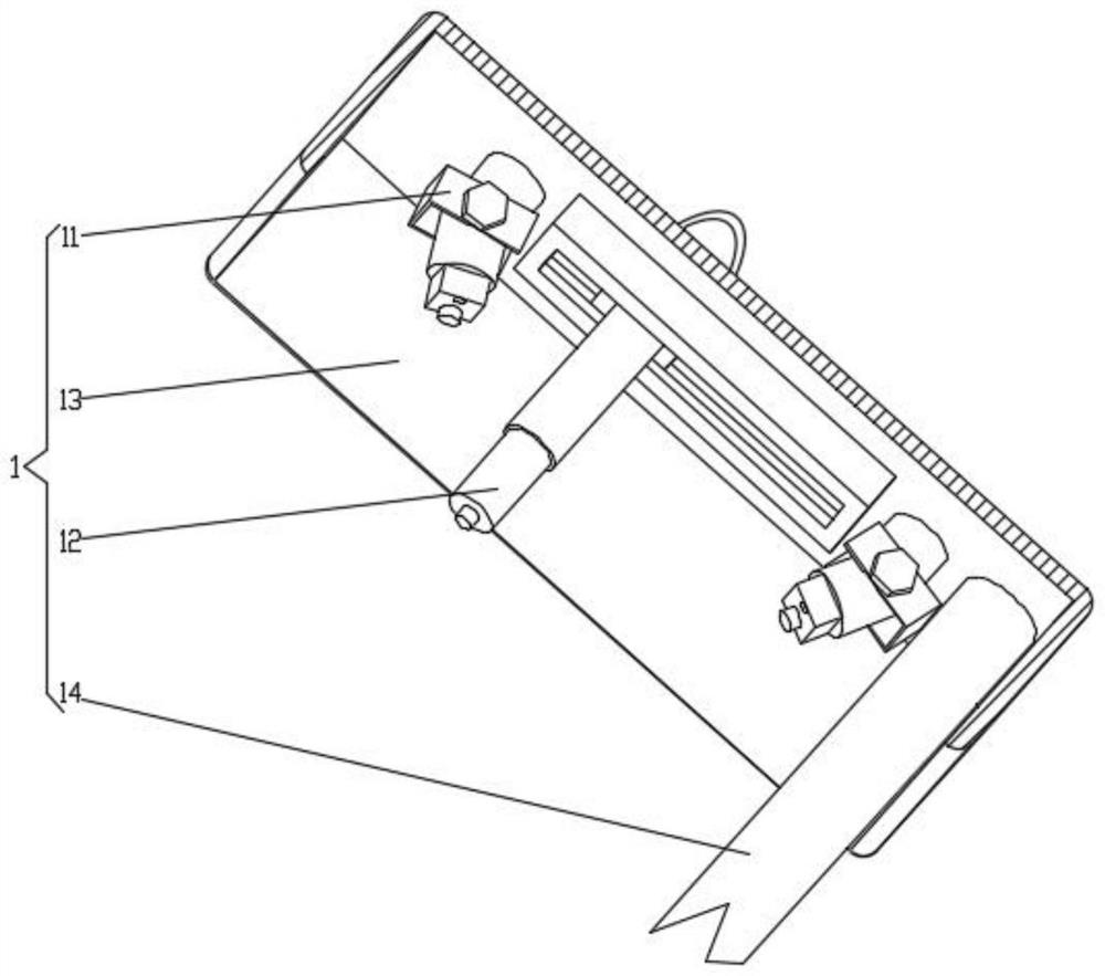
[0024] refer to Figure 1-2 A surgical navigation system for wound and dermatology particle skin detection and drilling is shown, including: a detection device 1, a PC terminal 2 and a folding bed 3, wherein the detection device 1 specifically includes a camera device 11 and a drilling device 12 , shading cover 13 and elevating rod 14, elevating rod 14 is fixedly connected with shading cover 13, camera device 11 is arranged on the inner cavity wall of shading cover 13, and shading cover 13 completely envelops camera device 11, avoids external light to camera device 11 Impact. Moreover, the camera device 11 is electrically connected to the PC terminal 2, the camera device 11 identifies the detection and drilling area, and transmits the identification information to the PC terminal 2, and the PC terminal is a graphics computer workstation.

[0025] The drilling device 12 is an electric telescopic rod, and the electric telescopic rod is electrically connected to the PC terminal ...

Embodiment 2

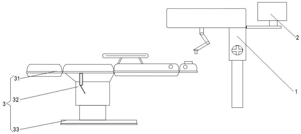
[0062] refer to Figure 3-4 A surgical navigation system for wound and dermatology particle skin detection and drilling is shown, including: a detection device 1, a PC terminal 2 and a folding bed 3, wherein the detection device 1 specifically includes a camera device 11 and a drilling device 12 , shading cover 13 and elevating rod 14, elevating rod 14 is fixedly connected with shading cover 13, camera device 11 is arranged on the inner cavity wall of shading cover 13, and shading cover 13 completely envelops camera device 11, avoids external light to camera device 11 Impact. Moreover, the camera device 11 is electrically connected to the PC terminal 2 , and the camera device 11 identifies the detection and drilling area, and transmits the identification information to the PC terminal 2 .

[0063] The drilling device 12 is a mechanical arm, and the mechanical arm is electrically connected to the PC terminal 2, and the PC terminal 2 controls the movement of the mechanical arm....


PUM


Abstract

The invention discloses a surgical navigation system for wound surface and dermatology department microparticle skin detection and drilling, the system comprises a detection device, a camera device, a drilling device and a light shield, the camera device is connected to the inner cavity wall of the light shield, and the camera device is electrically connected with a PC terminal; the first end of the drilling device is connected to the inner cavity wall of the light shield, the second end of the drilling device is provided with a drilling detection head, and the drilling detection head is electrically connected with the PC end; the drilling detection head rotates to push the obstacle aside, and a sensor used for detecting the point columnar particle skin is arranged at the tip end of the drilling detection head. According to the method, detection and drilling evaluation can be carried out on the point-column-shaped microdermis, application of point-column-shaped microdermis 3D treatment to wound transplantation, hair transplantation, pigment-deficient skin and scars is assisted, the survival rate of granulation wound planting is high, the effect of promoting wound healing is achieved, the problem of complex wound and skin repairing is solved, and the method is a novel planting method.

Description

[0001] The invention relates to the technical field of medical devices, and more specifically relates to a surgical navigation system for detection and drilling of wounds and dermatology microdermabrasion. Background technique [0002] In the treatment of deep burns, refractory wounds, and granulation wounds, we mostly use traditional surgical methods such as skin grafting or skin flap transfer, which have achieved certain results, but there are still many shortcomings. [0003] In recent years, with the development of society and economy and the acceleration of population aging process, the cases of wound repair due to traffic accidents, industrial injuries, etc. have continued to decline, while pressure sores (decubitus ulcers) There are more and more patients with chronic wounds such as diabetic feet and old rotten feet. These patients are either old and frail, or combined with multiple chronic diseases, and their general condition is poor. Wound repair is difficult, which ...

Claims


Application Information

Patent Timeline
Patent Type & Authority Applications(China)
IPC IPC(8): A61B34/20A61B17/322A61B34/00A61B34/30A61B90/00A61B90/14A61G13/06A61G13/08A61G13/10A61G13/12
CPCA61B34/20A61B17/322A61B90/06A61B90/14A61B34/30A61B34/70A61G13/06A61G13/08A61G13/10A61G13/12A61G13/121A61B2034/2055A61B2034/2065A61B2017/320052A61B2090/061A61B2090/062A61B2090/067
Inventor 孙雅丽胡雪剑吕国忠
Owner C&A LIGHT INT MEDICAL INVESTMENT MANAGEMENT BEIJING CO LTD
Learn More