
Servo driver switching power supply

A servo drive, switching power supply technology, applied in electrical components, springs/shock absorbers, vibration suppression adjustment, etc., can solve problems such as increasing device downtime, reducing device functionality, increasing workload, etc., to avoid damage to precision components , Improve the service life and reduce the effect of downtime

Pending Publication Date: 2022-05-06
湖北泰和电气有限公司
View PDF0 Cites 0 Cited by
  • Summary
  • Abstract
  • Description
  • Claims
  • Application Information

AI Technical Summary

Problems solved by technology

[0003] However, the existing switching power supply of the servo drive has loose wiring during use, and this situation cannot be intuitively understood by the staff, and the staff needs to check one by one, which increases the workload on the one hand, and affects the device on the other hand. maintenance efficiency, increase the downtime of the device, and reduce the practicability of the device. In addition, the existing switching power supply of the servo driver can understand the working data of the device by observing the data on the display screen during use, but when the external light is strong , causing the staff to be unable to clearly observe the data, affecting the performance of the device and reducing the functionality of the device. In addition, the existing switching power supply of the servo driver is easily affected by external vibrations during use, which in turn leads to damage to the precision components inside the device or connection If it is not tight, it will eventually cause the device to be unusable and reduce the service life of the device. Therefore, a switching power supply for servo drives is urgently needed to solve the existing problems

Method used


Image

  • Servo driver switching power supply
  • Servo driver switching power supply
  • Servo driver switching power supply

Examples


Embodiment Construction

[0036] The present invention will be further described below in conjunction with accompanying drawing:

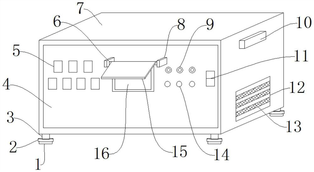
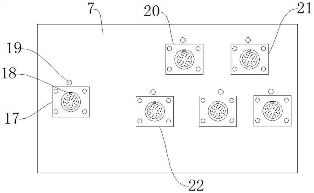
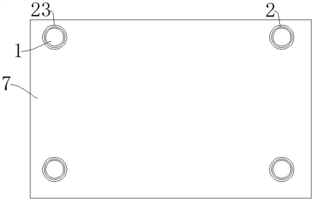
[0037] like Figure 1-Figure 4As shown, a switching power supply for a servo drive includes a power supply body 7, a bump 10, a telescopic column 3 and a spring 24. The bumps 10 are fixed on both side walls of the power supply body 7, and the bottom of the power supply body 7 Sleeves 23 are arranged at the four corners of the end, the telescopic column 3 is fixed inside the sleeve 23, the spring 24 is fixed on the outer wall of the telescopic column 3, and the bottom end of the telescopic column 3 is provided with a backing plate 2. A suction cup 1 is fixed at the bottom of the backing plate 2, an input interface 17 is arranged on the back wall of the power supply body 7, an output interface 22 is arranged on one side of the input interface 17, and a signal is arranged above the output interface 22. Interface 20, the signal interface 20 side is provided with a network inte...


PUM


Abstract

A servo driver switching power supply disclosed by the present invention comprises a power supply body, convex blocks, telescopic columns and springs, the convex blocks are fixed on the two side walls of the power supply body, sleeves are arranged at the four corners of the bottom end of the power supply body, the telescopic columns are fixed in the sleeves, the springs are fixed on the outer side walls of the telescopic columns, and the springs are fixed on the outer side walls of the telescopic columns. A base plate is arranged at the bottom end of the telescopic column. The device has the beneficial effects that the pressure switch and the warning lamp are arranged, in the wiring process, the connector of the connecting wire can apply pressure to the pressure switch, then the pressure switch controls the warning lamp to be turned on, and in the using process of the device, whether the connecting wire is loosened or not can be determined by observing the turning-on condition of the warning lamp; and workers do not need to check one by one, so that the workload of the workers is reduced, the checking efficiency of the workers is improved, the downtime of the device is shortened, and the practicability of the device is improved.

Description

technical field [0001] The invention relates to the technical field of a switching power supply for a servo driver, in particular to a switching power supply for a servo driver. Background technique [0002] Servo drive, also known as "servo controller" and "servo amplifier", is a controller used to control servo motors. Its function is similar to that of frequency converters on ordinary AC motors. The precise positioning system needs to be controlled by switching power supply during the use of the servo drive. [0003] However, the existing switching power supply of the servo drive has loose wiring during use, and this situation cannot be intuitively understood by the staff, and the staff needs to check one by one, which increases the workload on the one hand, and affects the device on the other hand. maintenance efficiency, increase the downtime of the device, and reduce the practicability of the device. In addition, the existing switching power supply of the servo driver...

Claims


Application Information

Patent Timeline
IPC IPC(8): H05K5/02H05K5/00F16F15/067
CPCH05K5/0247H05K5/0217H05K5/0234H05K5/0017F16F15/067
Inventor 骆仁星李军郑刚骆辰毛涪叶劲
Owner 湖北泰和电气有限公司
Learn More