Reactive compensation remote monitoring method based on transformer area intelligent fusion terminal

A remote monitoring and compensating controller technology, applied in the direction of reactive power adjustment/elimination/compensation, system integration technology, electrical components, etc., can solve the problems of power supply system security, insufficient intelligence level, low degree of automation, etc., to achieve Realize full-automatic monitoring and full-range dynamic adjustment, improve operation quality, and improve the effect of power factor

Pending Publication Date: 2022-05-06
安徽明生恒卓科技有限公司
View PDF0 Cites 0 Cited by
  • Summary
  • Abstract
  • Description
  • Claims
  • Application Information

AI Technical Summary

Problems solved by technology

[0003] In order to solve the problem that the reactive power compensation state monitoring method in the existing power supply system has a low degree of automation and the power supply system is insufficient in safety and intelligence; the invention provides a remote monitoring method for reactive power compensation based on the intelligent fusion terminal of the station area and its system

Method used


Image

  • Reactive compensation remote monitoring method based on transformer area intelligent fusion terminal
  • Reactive compensation remote monitoring method based on transformer area intelligent fusion terminal
  • Reactive compensation remote monitoring method based on transformer area intelligent fusion terminal

Examples


Embodiment 1

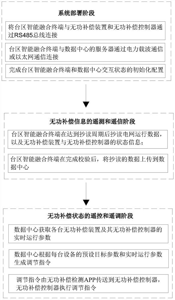
[0045] This embodiment provides a remote monitoring method for reactive power compensation based on an intelligent fusion terminal in a station area. The method is used to realize remote monitoring and control of the operating state of a reactive power compensation system. Such as figure 1 As shown, the remote monitoring method includes the following processes:

[0046] 1. System deployment stage:

[0047] The intelligent fusion terminal in the station area communicates with the reactive power compensation device and its reactive power compensation controller through the RS485 bus interface. The intelligent fusion terminal in the station area establishes a communication connection with the central server of a remote data center through power carrier communication or Ethernet. And complete the initial configuration of the interaction state between the intelligent fusion terminal and the data center in the station area.

[0048] 2. Telemetry and remote signaling stage of reac...

Embodiment 2

[0072] This embodiment provides a remote monitoring system for reactive power compensation based on the intelligent fusion terminal of the station area. Remote monitoring and control of the operating status of the power compensation system. Such as Figure 4 As shown, the remote monitoring system for reactive power compensation includes: an intelligent fusion terminal in the station area, a communication module, a data center, and a management terminal.

[0073] Among them, the intelligent fusion terminal in the station area is electrically connected with the reactive power compensation device and the reactive power compensation controller through the RS485 bus interface. Among them, the reactive power compensation device and the reactive power compensation controller are as follows: Figure 5 with Image 6 shown. The intelligent fusion terminal in the station area is used to collect the operating status information of the reactive power compensation device, and then obtai...


PUM


Abstract

The invention belongs to the field of power equipment, and particularly relates to a reactive compensation remote monitoring method and system based on a transformer area intelligent fusion terminal. The remote monitoring method is used for remotely monitoring and controlling the operation state of the reactive compensation system. Comprising the following steps: 1, a system deployment stage: a transformer area intelligent fusion terminal is connected with a reactive power compensation device and a reactive power compensation controller through an RS485 bus interface, and is connected with a data center through power line carrier communication or an Ethernet; 2, a telemetering and telesignaling stage of reactive compensation information: reading the operation state information of each device and uploading the operation state information to a data center by the transformer area intelligent fusion terminal; 3, a remote control and remote regulation stage of the reactive compensation state: the data center generates a regulation instruction according to the preset target parameter and the real-time operation parameter of each reactive compensation device; and the adjustment of the reactive compensation state of the transformer area is completed. The problems that a traditional reactive compensation state monitoring method is low in automation degree and insufficient in safety and intelligent level are solved.

Description

technical field [0001] The invention belongs to the field of electric equipment, and in particular relates to a remote monitoring method and system for reactive power compensation based on an intelligent fusion terminal in a station area. Background technique [0002] Reactive power compensation, the full name of reactive power compensation; in the power supply system, the power factor of the power grid is usually improved through reactive power compensation devices, and the loss of power supply transformers and transmission lines is reduced; thereby achieving the purpose of improving power supply efficiency and power supply environment . The reactive power compensation device is an indispensable device in the power supply system. Reasonable selection of compensation devices can minimize the loss of the power grid and improve the quality of the power grid. On the contrary, if it is improperly selected or used, it may cause problems such as power supply system, voltage fluc...

Claims


Application Information

Patent Timeline
IPC IPC(8): H02J3/18H02J13/00
CPCH02J3/18H02J13/00002H02J13/00001H02J13/00032Y02E40/70Y02E60/00Y04S10/22Y04S40/124
Inventor 蒋志刚郝雨陈昊王明徐晓波王记强章亚辉
Owner 安徽明生恒卓科技有限公司
Why Eureka
Try Eureka