
Direct current test system and test voltage acquisition method

A technology of DC test and test voltage, applied in the direction of motor generator test, etc., can solve the problems of insufficient capacity of low-voltage closing switch and difficult to realize voltage acquisition.

Pending Publication Date: 2022-05-06
GANSU ELECTRIC APP RES INST
View PDF0 Cites 0 Cited by
  • Summary
  • Abstract
  • Description
  • Claims
  • Application Information

AI Technical Summary

Problems solved by technology

Because there is no DC circuit breaker with high breaking capacity, the capacity of the low-voltage closing switch is insufficient, and it is impossible to independently control the on and off of the test power supply. In the large-capacity DC test, the power supply cannot be directly controlled on the DC side. The AC side controls the power on and off, which makes it relatively difficult to realize the voltage acquisition in the DC test

Method used


Image

  • Direct current test system and test voltage acquisition method
  • Direct current test system and test voltage acquisition method
  • Direct current test system and test voltage acquisition method

Examples


Embodiment Construction

[0024] The present invention will be described in further detail below in conjunction with the accompanying drawings.

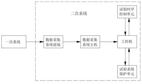
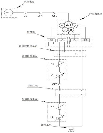
[0025] Such as figure 1 , figure 2 A DC test system shown includes a primary system and a secondary system. The primary system includes a high-voltage AC isolating switch QS, an opening high-voltage AC circuit breaker QF1, a closing high-voltage AC circuit breaker QF2, and a high-voltage AC isolating switch QS in series. It is connected to the AC power supply, the closing high-voltage AC circuit breaker QF2 is connected to the step-down transformer, and the step-down transformer is connected to the rectifier cabinet. The rectifier cabinet rectifies the input AC power into DC power and outputs it to the series-parallel conversion units in series, The front-stage impedance unit, low-voltage DC circuit breaker QF3, test station and post-stage impedance unit, the end of the post-stage impedance unit is grounded; the two sides of the low-voltage DC circuit break...


PUM


Abstract

The invention discloses a DC test system and a test voltage acquisition method, and the DC test system comprises a primary system and a secondary system. The primary system comprises a high-voltage alternating-current isolating switch QS, an opening high-voltage alternating-current circuit breaker QF1, a closing high-voltage alternating-current circuit breaker QF2, a step-down transformer, a rectifier cabinet, a series-parallel conversion unit, a pre-stage impedance unit, a low-voltage direct-current circuit breaker QF3, a test station and a post-stage impedance unit which are sequentially connected in series, and the tail end of the post-stage impedance unit is grounded; the rectifier cabinet rectifies an input alternating current power supply into a direct current power supply and outputs the direct current power supply to the low-voltage direct current circuit breaker QF3, two sides of the low-voltage direct current circuit breaker QF3 are respectively connected with the secondary system through optical fibers, and the front end of the data acquisition system acquires test voltage signals in the period from closing of the closing high-voltage alternating current circuit breaker QF2 to closing of the low-voltage direct current circuit breaker QF3 through optical fibers. And the voltage signals are transmitted to the data acquisition system host and the industrial personal computer for signal identification, processing and display.

Description

technical field [0001] The invention relates to the technical field of switching electrical appliances detection, in particular to a DC test system and a test voltage collection method. Background technique [0002] In recent years, with the development of DC transmission technology and distributed energy, the advantages of DC power supply have become more prominent, which has further promoted the development of DC electrical appliances. Various switching appliances such as DC circuit breakers, DC contactors, and DC fuses have been used in DC. system. Short-circuit test, on-off test, and electrical life test are important type tests for DC switching devices. In DC tests, voltage, current, and time constant are important test parameters. Among them, the current can be collected by shunts, Hall sensors, etc., and the time constant can be Calculated and read out in waveform graph. Since there is no DC circuit breaker with high breaking capacity, the capacity of the low-voltag...

Claims


Application Information

Patent Timeline
Patent Type & Authority Applications(China)
IPC IPC(8): G01R31/34
CPCG01R31/34
Inventor 康志林李涛李勇魏慧慧罗园漆昀晟缑剑吴永洋张艳景智琪
Owner GANSU ELECTRIC APP RES INST
Learn More