
Bridge sewer pipe repairing equipment and using method thereof

A technology for water pipes and bridges, which is applied in the field of repairing equipment for water pipes under bridges. It can solve the problems of large manpower input, falling into the eyes of maintenance personnel, unfavorable and safe maintenance of water pipes, etc., and achieve the effect of ensuring safety.

Pending Publication Date: 2022-05-06
HENAN PROVINCIAL COMM PLANNING & DESIGN INST CO LTD
View PDF0 Cites 0 Cited by
  • Summary
  • Abstract
  • Description
  • Claims
  • Application Information

AI Technical Summary

Problems solved by technology

[0002] After long-term use of the water pipes under the bridge, some cracks or holes will appear on the outer wall of the water pipe. When repairing the damaged water pipe, the maintenance personnel generally need to wipe the outside of the hole of the water pipe with a rag, and then apply glue to the outside of the hole of the water pipe. The repair segment is bonded to the outside of the hole, and finally the repair segment and the water pipe are fixed again with clamps. The entire water pipe repair process requires a lot of manpower, which increases the burden on maintenance personnel, and the water pipe under the bridge is generally located at a high position. It is necessary to use an external lifting device to send the maintenance personnel to the location of the water pipe. The maintenance personnel need to maintain the water pipe with both hands while raising their head. The dust and glue falling from the water pipe will directly fall on the maintenance personnel, and sometimes even fall into the maintenance personnel’s eyes Inside, it is not conducive to the safe maintenance of water pipes, thus affecting the work efficiency of water pipe repairs

Method used


Image

  • Bridge sewer pipe repairing equipment and using method thereof
  • Bridge sewer pipe repairing equipment and using method thereof
  • Bridge sewer pipe repairing equipment and using method thereof

Examples


Embodiment Construction

[0039] The technical solutions in the embodiments of the present invention will be clearly and completely described below in conjunction with the embodiments of the present invention. Apparently, the described embodiments are only some of the embodiments of the present invention, not all of them. Based on the embodiments of the present invention, all other embodiments obtained by persons of ordinary skill in the art without creative efforts fall within the protection scope of the present invention.

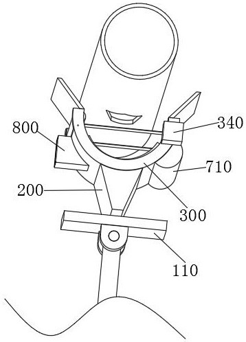
[0040] see Figure 1-11 As shown, a bridge sewer pipe repair equipment includes an electric push rod 100, the top of the electric push rod 100 is rotatably connected to a support plate 110, the top surface of the support plate 110 is slidably connected to a support shell 200, and the open end of the support shell 200 is An arc-shaped supporting plate 300 is fixedly connected, and a repair segment 400 is placed on the top surface of the arc-shaped supporting plate 300. Both ends of...


PUM


Abstract

The invention relates to the technical field of bridge sewer pipe repairing, in particular to bridge sewer pipe repairing equipment and a using method thereof.The bridge sewer pipe repairing equipment comprises an electric push rod, the top end of the electric push rod is rotationally connected with a supporting plate, the top face of the supporting plate is slidably connected with a supporting shell, and the open end of the supporting shell is fixedly connected with an arc-shaped supporting plate; a repairing segment is placed on the top face of the arc-shaped supporting plate, two symmetrically-distributed telescopic rods are fixedly connected to the middle of the bottom face of the arc-shaped supporting plate, a second conveying roller is rotationally connected between the two telescopic rods, and a conveying belt is in transmission connection between the first conveying roller and the second conveying roller. According to the device, the glue injection barrel is rotated to enable the glue outlet hole in the glue injection barrel to face the micro brush, glue is put on the micro brush, the micro brush coats the glue on the outer side wall of the micro brush to the outer side of a water pipe repairing position along with continuous movement of the conveying belt, manual glue coating is omitted, the glue coating efficiency is improved, and the glue is also prevented from dripping from a high position.

Description

technical field [0001] The invention relates to the technical field of bridge sewer pipe repair, in particular to bridge sewer pipe repair equipment and a method for using the same. Background technique [0002] After long-term use, the outer wall of the water pipe under the bridge will have cracks or holes. When repairing the damaged water pipe, the maintenance personnel generally need to wipe the outside of the hole of the water pipe with a rag, and then apply glue to the outside of the hole of the water pipe. The repair segment is bonded to the outside of the hole, and finally the repair segment and the water pipe are fixed again with a clamp. The entire water pipe repair process requires a lot of manpower, which increases the burden on the maintenance personnel, and the water pipe under the bridge is generally located at a high position. It is necessary to use an external lifting device to send the maintenance personnel to the location of the water pipe. The maintenance ...

Claims


Application Information

Patent Timeline
Patent Type & Authority Applications(China)
IPC IPC(8): F16L55/18F16L55/175B08B9/023
CPCF16L55/18F16L55/175B08B9/023
Inventor 王澍湉刘星环刘艮云徐天昭李贺刘璐璐张丙钦颜超
Owner HENAN PROVINCIAL COMM PLANNING & DESIGN INST CO LTD
Learn More