Phase locked loop circuit

A phase-locked loop and circuit technology, applied in the direction of electrical components, automatic power control, etc., can solve problems such as the increase in the number of terminals and the increase in circuit size.

Inactive Publication Date: 2004-03-31
NEC ELECTRONICS CORP
View PDF1 Cites 2 Cited by
  • Summary
  • Abstract
  • Description
  • Claims
  • Application Information

AI Technical Summary

Problems solved by technology

[0032] However, as described above, there are some problems in switching between gains in conventional PLL circuits, such as an increase in the number of terminals and an increase in circuit size

Method used


Image

  • Phase locked loop circuit
  • Phase locked loop circuit
  • Phase locked loop circuit

Examples


Embodiment Construction

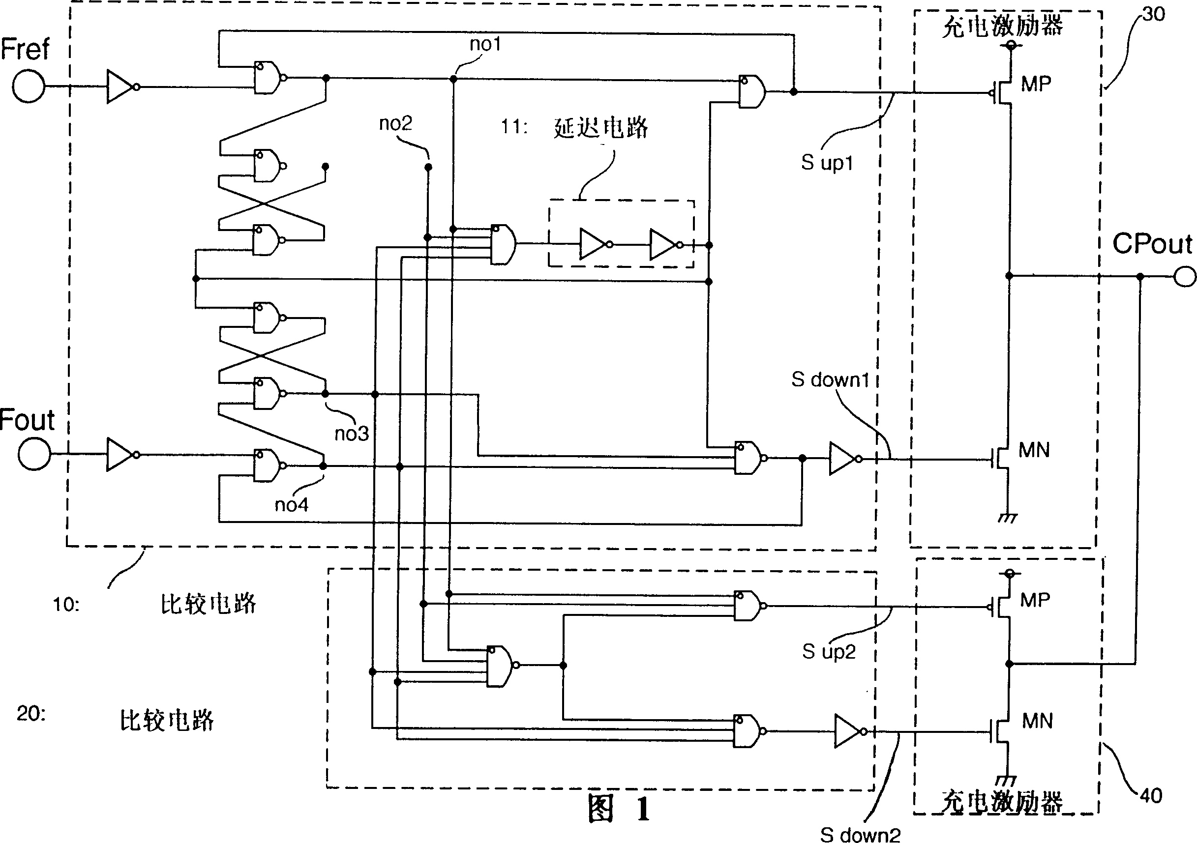
[0052] The present invention will be described below. FIG. 1 is a schematic structural connection diagram of an example of a PLL circuit according to a first embodiment of the present invention. It can be seen that the structure of the feedback circuit of the PLL circuit adopted by the embodiment of the present invention is similar to the conventional one, so the diagram and detailed description of the feedback circuit are omitted.

[0053] In FIG. 1, reference numerals 10 and 20 denote comparison circuits. Among these comparison circuits, the comparison circuit 10 has the characteristic of having no dead zone, and the oscillation signal F output from a voltage-controlled oscillator (not shown) out is input to the compare circuit.

[0054] These comparison circuits, comparison circuits 10 and 20 are circuits using logic gates and FF (flip-flop) circuits and similar circuits, as in US Patent 4,281,259 and IEEE Document, Volume CE-27, No. 3, pp. As shown in the August edition...


PUM


Abstract

A phase locked loop circuit is provided, in which frequencies and phase differences between the oscillation output of a voltage control oscillation means and a reference signal are compared by a first comparison means, a first charging exciter charges and discharges based on the comparison result, frequencies and phase differences between the oscillation output of the voltage control oscillation means and the reference signal are also compared by a second comparison means, and a second charging exciter charges and discharges based on the comparison result. The gain of the phase difference versus outputting voltage characteristic of the second comparison means and the second charging exciter are higher than that of the first comparison means and the first charging exciter, and the second comparison means has a dead zone in said phase difference versus outputting voltage characteristic. A first delaying circuit for resolving the dead zone is inserted into the first comparison means.

Description

technical field [0001] The invention relates to a phase-locked loop circuit. Background technique [0002] Figure 5 is a block diagram of an example of a conventional phase-locked loop circuit (PLL). Such as Figure 5 As shown, the phase-locked loop circuit, which is usually a feedback circuit, includes a comparison circuit (phase-frequency comparison circuit) 51, a charge driver 52, a low-pass filter (LPF) 53, a voltage-controlled oscillator (VCO) 54 and a frequency division circuit 55. [0003] The above-mentioned comparison circuit 51 takes the externally input reference signal F ref and a signal F output by the frequency dividing circuit 55 out2 compared and output a control signal S up and a control signal S down , the amplitudes of these control signals have such that the reference signal F ref with signal F out2 There is a tendency for the difference in phase and frequency between them to decrease proportionally. [0004] The charging excitation circuit 52 is...

Claims


Application Information

Patent Timeline
IPC IPC(8): H03L7/087H03L7/089
CPCH03L7/0895H03L7/087H03L7/08
Inventor 川口学
Owner NEC ELECTRONICS CORP
Why Eureka
Try Eureka