Environment-friendly laser welding equipment capable of achieving limiting and damping effects of clamping piece
A laser welding, environmentally friendly technology, used in laser welding equipment, welding equipment, metal processing equipment and other directions, can solve problems such as the limit of workpieces that cannot be welded, and achieve the effect of reducing defective products and preventing shaking
- Summary
- Abstract
- Description
- Claims
- Application Information
AI Technical Summary
Problems solved by technology
Method used
Image
Examples
Embodiment 1
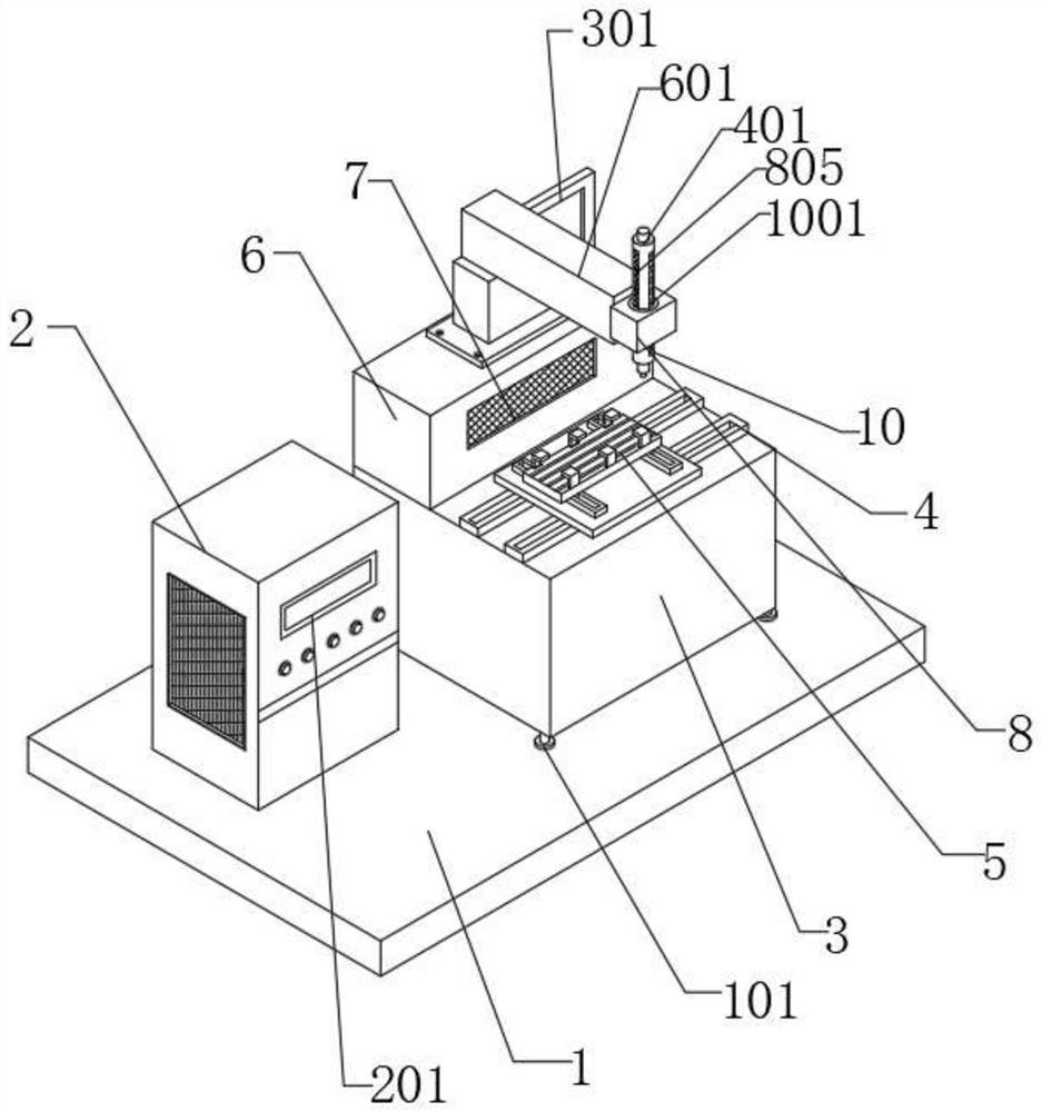
[0032] Example 1: See figure 1 and Figure 4, an environment-friendly laser welding equipment that can achieve the effect of limiting and reducing vibration of clamping parts, including a base plate 1, a body 3, a workbench 5 and a regulator 8, a box 2 is installed on the top of the base plate 1, and the base plate 1 is a pair of boxes 2 has a supporting function, the top of the body 3 is equipped with a support block 6, the body 3 provides installation space for the support block 6, the top of the body 3 is installed with a slide rail 4, and the slide rail 4 is located on one side of the support block 6, the slide rail 4 A workbench 5 is installed on the top of the body, the body 3 provides installation space for the slide rail 4, the slide rail 4 is convenient for the movement of the workbench 5, the workbench 5 is used to place the workpiece for welding, and the inner wall of the support block 6 is installed with a filter 7 to support Block 6 provides installation space fo...
Embodiment 2
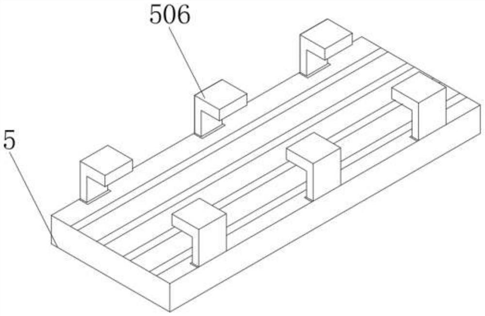
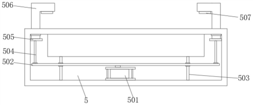
[0033] Example 2: see figure 2 and image 3 The inner wall of the workbench 5 is equipped with a cylinder 501, the top of the cylinder 501 acts as a supporting plate 502, the inner wall of the supporting plate 502 is installed with a guide rod 503, the top of the supporting plate 502 is equipped with a connecting rod 504, and the top of the connecting rod 504 is equipped with a connecting rod. Plate 505, the top of connecting plate 505 is equipped with a plurality of sets of limit blocks 506, the bottom of limit block 506 acts as a protective plate 507, the workbench 5 provides installation space for the cylinder 501, the cylinder 501 facilitates the movement of the support plate 502, and the guide rod 503 pairs The support plate 502 has a guiding function, and the support plate 502 provides an installation space for the connecting rod 504. The connecting rod 504 has a supporting effect on the connecting plate 505. In the installation space, when the welder 401 welds the wor...
Embodiment 3
[0034] Example 3: See Figure 5 , Figure 6 and Figure 7 Two sets of support frames 801 are installed on the inner wall of the regulator 8, and the outer wall of the support frame 801 is equipped with a servo motor 802, and the inner wall of the support frame 801 is installed with a support rod 803, and the output end of the servo motor 802 and one end of the support rod 803 pass through Belt transmission connection, the outer wall of the support rod 803 is surrounded by gears 804, two sets of racks 805 are installed on the outer wall of the welder 401, and the racks 805 are meshed with the gears 804, the adjuster 8 provides installation space for the support frame 801, supports The frame 801 provides installation space for the servo motor 802, the servo motor 802 provides power for the rotation of the gear 804, the support frame 801 provides the installation space for the support rod 803, the support frame 801 facilitates the rotation of the support rod 803, and the support...
PUM
 Abstract
Description
Claims
Application Information
 - R&D Engineer
- R&D Manager
- IP Professional
- Industry Leading Data Capabilities
- Powerful AI technology
- Patent DNA Extraction
Browse by: Latest US Patents, China's latest patents, Technical Efficacy Thesaurus, Application Domain, Technology Topic, Popular Technical Reports.
© 2024 PatSnap. All rights reserved.Legal|Privacy policy|Modern Slavery Act Transparency Statement|Sitemap|About US| Contact US: help@patsnap.com


