
Push-pull force testing device for intelligent electric energy meter

A technology of push-pull force test and smart electric energy meter, which is applied in the direction of measuring device, application of stable tension/pressure test material strength, instrument, etc. It can solve the problems of inconvenient observation and difficult observation of pressure changes, etc., so as to facilitate detection , fast and accurate detection, and the effect of ensuring the stability of the transmission

Inactive Publication Date: 2022-04-29
NINGBO UNIVERSITY OF TECHNOLOGY
View PDF0 Cites 2 Cited by
  • Summary
  • Abstract
  • Description
  • Claims
  • Application Information

AI Technical Summary

Problems solved by technology

[0003] According to the provisions of Article 8.5 of the State Grid Unidirectional Smart Energy Meter Type Specification Q / CDW 1355-2003: when the voltage and current terminals are subjected to an axial pressure of 60N, the terminals should not be loosened or displaced. The existing thrust test is mainly It is done by manually loading and observing the deformation with the naked eye. There are also a small number of automatic pressure-applying machines, but it is difficult for automatic pressure-applying machines to observe pressure changes, and it is inconvenient to intuitively monitor real-time pressure changes during testing. Observed

Method used


Image

  • Push-pull force testing device for intelligent electric energy meter
  • Push-pull force testing device for intelligent electric energy meter
  • Push-pull force testing device for intelligent electric energy meter

Examples


Embodiment Construction

[0026] The following will clearly and completely describe the technical solutions in the embodiments of the present invention with reference to the accompanying drawings in the embodiments of the present invention. Obviously, the described embodiments are only some, not all, embodiments of the present invention. Based on the embodiments of the present invention, all other embodiments obtained by persons of ordinary skill in the art without making creative efforts belong to the protection scope of the present invention.

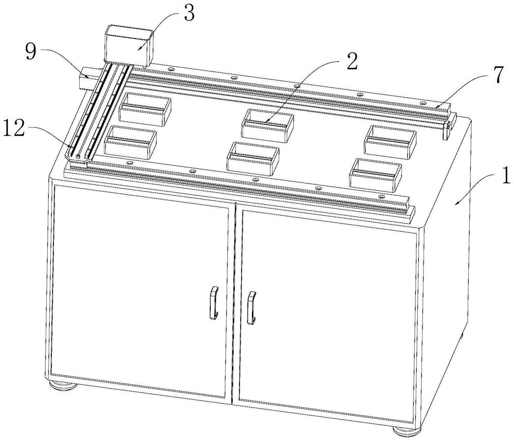
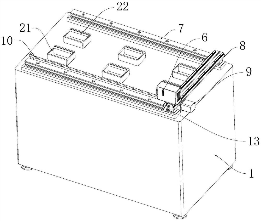
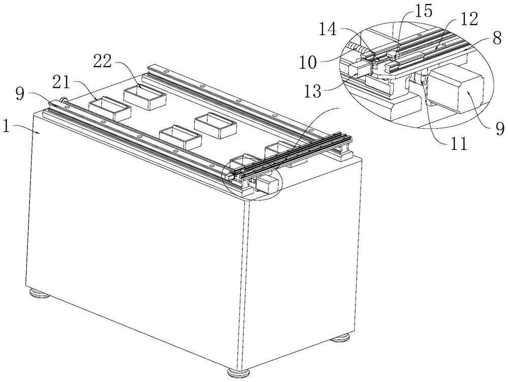
[0027] see Figure 1-9 , the present invention provides a technical solution: a push-pull test device for smart electric energy meters, including a base 1, a positioning part 2 for fixing the electric energy meter is arranged on the base 1, a detection box 3 is movable on the base 1, and the detection box 3 is provided with a pressure-applying mechanism 4, which applies pressure to the terminals of the electric energy meter through the pressure-applying mechan...


PUM


Abstract

The invention discloses a push-pull force testing device for an intelligent electric energy meter, which comprises a base, a positioning piece for fixing the electric energy meter is arranged on the base, a detection box is movably arranged on the base, a pressure applying mechanism is arranged in the detection box, and a terminal of the electric energy meter is pressed through the pressure applying mechanism. The push-pull force testing device comprises a detection box, a pressure applying mechanism is arranged on the outer wall of the detection box, an amplifying mechanism is arranged in the detection box, the amplifying mechanism is in transmission connection with the pressure applying mechanism, an observation piece used for observing pressure change is arranged on the outer wall of the detection box, and the observation piece is in transmission connection with the amplifying mechanism. According to the electric energy meter terminal stress detection device, original tiny displacement during pressure application can be amplified, detection personnel can conveniently observe the pressure change condition, the stress condition of the electric energy meter terminal can be better reflected, the LED lamp is arranged, the pressure change condition can also be reflected through the brightness change of the LED lamp during pressure application, and the detection personnel can more accurately and rapidly detect the electric energy meter terminal.

Description

technical field [0001] The invention relates to the technical field of testing devices, in particular to a push-pull force testing device for smart electric energy meters. Background technique [0002] With the rise of smart grid construction in countries all over the world, smart energy meters, as the terminals of smart grids, have been widely promoted and applied in countries all over the world. The accuracy and reliability of smart energy meter measurements are still the focus of attention. It directly affects For the economic interests of power generation companies, power supply companies and power customers, thrust testing is a very important full-performance test item in the quality control of smart energy meters. [0003] According to Article 8.5 of the State Grid Unidirectional Smart Electric Energy Meter Type Specification Q / CDW 1355-2003: When the voltage and current terminals are subjected to an axial pressure of 60N, the terminals should not be loosened or displa...

Claims


Application Information

Patent Timeline
Patent Type & Authority Applications(China)
IPC IPC(8): G01N3/08G01N3/02
CPCG01N3/08G01N3/02
Inventor 安鹏李庆风郑悠
Owner NINGBO UNIVERSITY OF TECHNOLOGY
Learn More