
Novel anti-seismic steel structure

An anti-seismic steel, a new type of technology, applied in the direction of anti-seismic, building types, building components, etc., can solve the problems of loose seismic steel structure, structural looseness, and large limitations of seismic structure, so as to protect its own structure and solve the effect of structural looseness.

Pending Publication Date: 2022-04-29
彭泽鑫
View PDF0 Cites 0 Cited by
  • Summary
  • Abstract
  • Description
  • Claims
  • Application Information

AI Technical Summary

Problems solved by technology

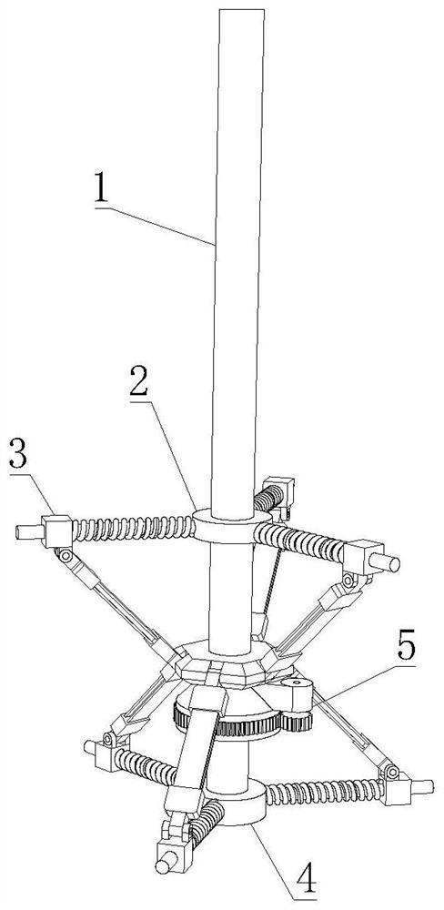
[0005] The present invention provides a new type of anti-seismic steel structure, one of the purposes of which is to have the function of rationally adjusting the shape of the new type of anti-seismic structure according to the actual situation, and solve the problem that the existing anti-seismic structure has relatively large limitations and cannot be used flexibly after the structure and function change; Another purpose is to solve the problem of structural looseness caused by the shaking of the seismic steel structure during the earthquake, so as to achieve the effect of buffering the shaking, thereby reducing vibration and protecting its own structure; another purpose is to strengthen the connecting steel plate itself Respond to the strength and stability of the vibration, and solve the problem of loosening and deformation of the structure caused by the shaking of the steel during the earthquake; one of the purposes is to solve the problem of the locking of the structure during the adjustment process of the seismic structure, so as to achieve stable locking and earthquake resistance The effect of not deforming the structure

Method used


Image

  • Novel anti-seismic steel structure
  • Novel anti-seismic steel structure
  • Novel anti-seismic steel structure

Examples


Embodiment 1

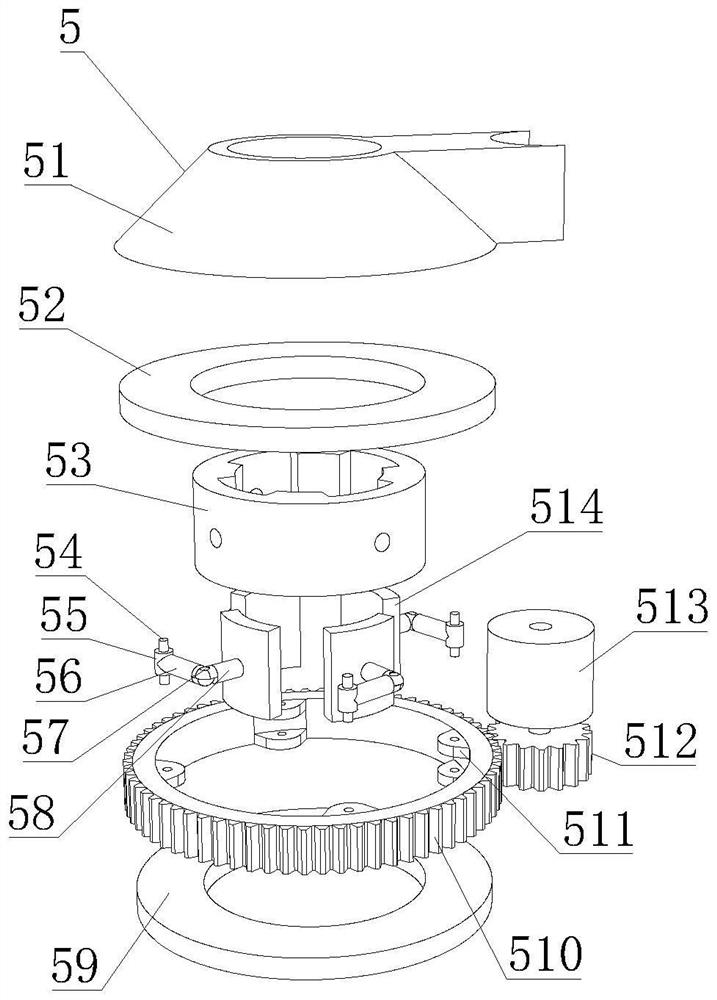
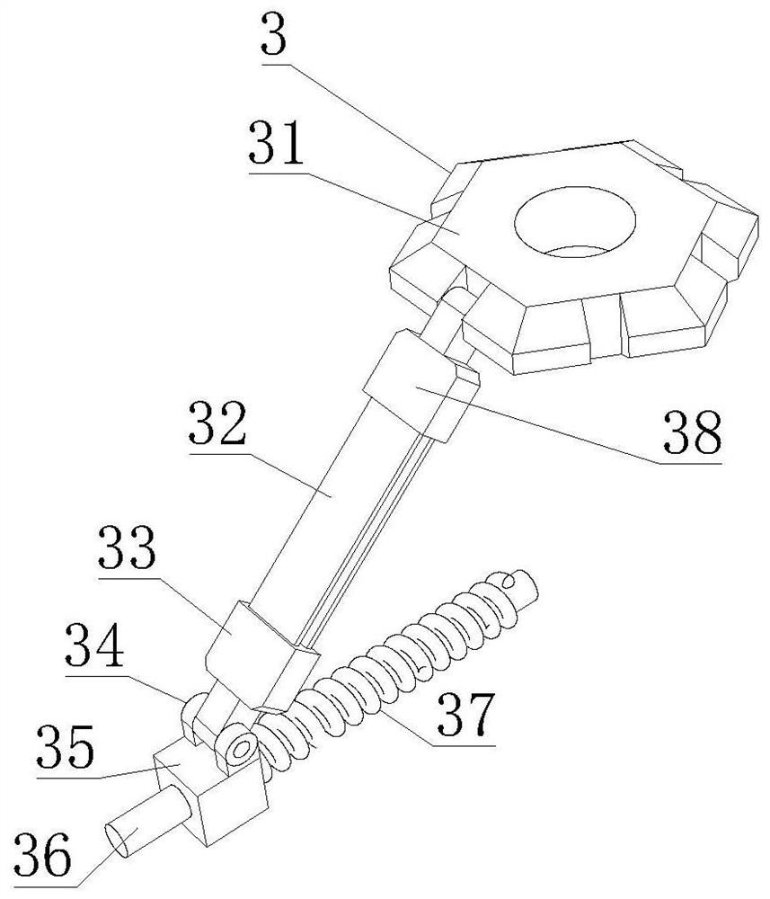
[0037] like Figure 1-7 As shown, the present invention provides a novel anti-seismic steel structure, comprising a supporting steel column 1, the lower side of the supporting steel column 1 is fixedly connected with a fixed base 4, and the outer surface of the fixed base 4 is fixedly connected with an anti-seismic mechanism 3, and the anti-seismic mechanism 3 Including an I-shaped plate mechanism 32 and a vibration-damping ring mechanism 34, the I-shaped plate mechanism 32 includes a built-in shock absorbing bar mechanism 322, and the built-in shock absorbing bar mechanism 322 includes an octagonal ring 3227, and the inner side of the octagonal ring 3227 is fixedly connected with an elliptical ring piece 3228, the outer surface of the supporting steel column 1 is movably connected with a locking mechanism 5, the locking mechanism 5 includes a gear ring 510, the inner wall of the gear ring 510 is fixedly connected with a connecting block 511, the lower side of the anti-seismic ...

Embodiment 2

[0040] like Figure 1-7 As shown, on the basis of Embodiment 1, the present invention provides a technical solution: preferably, the inner side of the elliptical ring piece 3228 is fixedly connected with a wave elastic piece 3226, and the side of the octagonal ring 3227 is fixedly connected with a connecting rod 3223. The interior of the rod 3223 is fixedly connected with a reinforced vertical rod 3222, and the two ends of the reinforced vertical rod 3222 are fixedly connected with a reinforced long rod 3221. The side is fixedly connected with a right curved elastic sheet 3225, and the right side of the right curved elastic sheet 3225 is fixedly connected with the outer surface of the reinforced long rod 3221, and the outer side of the built-in shock absorber mechanism 322 is fixedly connected with an I-shaped board shell 321.

[0041] In this embodiment, the frame of the internal structure is composed of the reinforced long rod 3221, the reinforced vertical rod 3222 and the c...

Embodiment 3

[0043] like Figure 1-7 As shown, on the basis of Embodiment 1, the present invention provides a technical solution: preferably, the lower end of the I-shaped plate mechanism 32 is fixedly connected with a lower end cap mechanism 33, and the inside of the lower end cap mechanism 33 is provided with an I-shaped groove 331, The right end of the lower end cap mechanism 33 is internally connected with an orbiting shaft 332. The damping ring mechanism 34 includes a fan-shaped elastic steel sheet 345. One side of the fan-shaped elastic steel sheet 345 is fixedly connected with a connecting ring 346. The inner wall of the connecting ring 346 is connected to the orbiting shaft. The outer surface of the shaft 332 is rotatably connected, the outer side of the connecting ring 346 is fixedly connected with a damping spring 344, and the other side of the damping spring 344 is fixedly connected with a damping ring shell 341, and the inner wall of the damping ring shell 341 is connected to th...


PUM


Abstract

The invention discloses a novel anti-seismic steel structure, and relates to the technical field of steel structure anti-seismic innovation, the novel anti-seismic steel structure comprises a supporting steel column, the lower side of the supporting steel column is fixedly connected with a fixed base, the outer surface of the fixed base is fixedly connected with an anti-seismic mechanism, and the anti-seismic mechanism comprises an I-shaped plate mechanism and a vibration reduction ring mechanism; the I-shaped plate mechanism comprises a built-in damping strip mechanism, the built-in damping strip mechanism comprises an octagonal ring, the outer surface of the supporting steel column is movably connected with a locking mechanism, and the locking mechanism comprises a gear ring. A hexagonal movable block is moved up and down, so that an I-shaped plate mechanism does fan-shaped rotation around an upper end cap mechanism, a lower end cap mechanism drives a vibration reduction ring mechanism, a sliding block slides on a sliding rod, and therefore the height of an anti-seismic mechanism in the vertical direction is adjusted, and the problems that an existing anti-seismic structure is large in limitation and poor in anti-seismic performance are solved. And the effect of reasonably adjusting the form and the position of the novel anti-seismic structure according to the actual situation is achieved.

Description

technical field [0001] The invention relates to the technical field of anti-seismic innovation of steel structures, in particular to a novel anti-seismic steel structure. Background technique [0002] Seismic structure is the most critical issue that should be considered in seismic design. It plays a decisive role in safety and economy and is a comprehensive system decision. The seismic performance of a structure refers to the bearing capacity, deformation capacity, energy dissipation capacity, and Changes and developments in stiffness and failure patterns. There are following problems at prior art: [0003] 1. The existing anti-seismic steel structures are generally limited and can only be used in limited structures. After structural and functional changes, the anti-seismic structure cannot continue to be used. The limitations are too large and cannot be flexibly changed. Some anti-seismic structures can only Only the structure is stable and lacks the function of vibratio...

Claims


Application Information

Patent Timeline
Patent Type & Authority Applications(China)
IPC IPC(8): E04B1/98E04H9/02E04C3/32
CPCE04B1/98E04H9/02E04C3/32
Inventor 彭泽鑫
Owner 彭泽鑫
Learn More