
Novel prefabricated box girder loading operation method

A box girder and girder installation technology, which is applied in bridges, bridge construction, erection/assembly of bridges, etc., can solve the problem of idle single-girder single-door beam handling beam machines in enterprises, inability to use new and old equipment together, and inability to span low-level beam transport vehicles. and other problems to achieve the effect of reducing the risk of hoisting operations, saving fuel consumption, and avoiding idle scrap.

Pending Publication Date: 2022-04-29
中铁十四局集团青岛工程有限公司 +1
View PDF0 Cites 1 Cited by
  • Summary
  • Abstract
  • Description
  • Claims
  • Application Information

AI Technical Summary

Problems solved by technology

However, the single-girder single-door beam handling machine has a limited span (generally 37-39 meters), so it cannot be loaded on a low-level beam transporter or an ultra-low beam transporter.
In the working conditions equipped with low-level beam transport vehicles or ultra-low beam transport vehicles, it is necessary to configure single-beam double-door or double-beam double-door beam handling machines, resulting in the company’s single-beam single-door beam handling machines being idle. Or procurement to meet the needs will greatly increase the construction cost of the enterprise. The above phenomenon is mainly due to the inability to use new and old equipment in the field of high-speed rail bridge erection construction

Method used


Image

  • Novel prefabricated box girder loading operation method
  • Novel prefabricated box girder loading operation method
  • Novel prefabricated box girder loading operation method

Examples


Embodiment 1

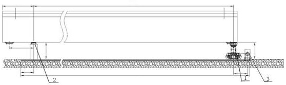
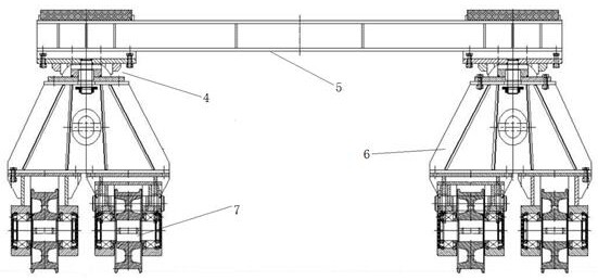
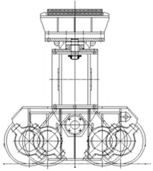
[0041] Such as figure 1 Among them, the beam loading trolley 1, the fixed beam platform 2 and the winch 3 arranged in the beam loading platform; figure 2 and image 3 They are the left view and the top view of the beam loading trolley 1, respectively. The beam loading trolley 1 is an existing product, and its structure includes a spherical joint support 4, a beam 5, a bracket 6, and a traveling steel wheel 7; Figure 4 It is a schematic diagram of the concrete buttress for the beam loading platform.

[0042] The specific embodiment of the beam loading platform operation of the present invention, in conjunction with such Figure 5 to Figure 10 To further illustrate the present invention, the devices used include a fixed beam platform 2, a beam loading trolley 1, a beam handling machine 10, a beam transport vehicle 9, a jacking device, a front camel beam trolley, a rear camel beam trolley, and a front camel beam trolley. The beam trolley and the rear camel beam trolley belon...


PUM


Abstract

The invention discloses a novel prefabricated box girder loading operation method, used devices comprise a fixed girder platform, a girder loading trolley, a girder carrying machine, a girder transporting vehicle, a jacking device, a front girder carrying trolley and a rear girder carrying trolley, and the novel prefabricated box girder loading operation method comprises the specific steps that firstly, the fixed girder platform and the girder loading trolley are arranged in the girder loading platform according to the specification of a box girder; secondly, the girder carrying machine carries the multiple box girders to the girder loading platform position; 3, aligning the girder transporting vehicle with the girder loading platform, and enabling the rear beam carrying trolley to replace the fixed girder platform for bearing; 4, when the girder transporting vehicle moves the box girder into the frame, enabling the front beam carrying trolley to replace the girder loading trolley for bearing through a jacking device after the rear beam transporting vehicle is limited; and fifthly, the box girder is completely moved into the frame through the girder transporting vehicle, and girder loading is completed. According to the method, old equipment is activated, idling and scrapping are avoided, meanwhile, the utilization rate of the beam carrying machine is remarkably increased, the hoisting operation risk is reduced, the beam field planning pressure is relieved, and cost is saved.

Description

technical field [0001] The invention relates to the technical field of bridge construction, in particular to a novel prefabricated box girder installation method. Background technique [0002] At present, with the continuous emergence of tunnel beam transport conditions, low-level and ultra-low beam transport vehicles have been put into use, but the low-level beam transport vehicles and ultra-low beam transport vehicles are designed to have the same bearing capacity due to the reduction in vehicle height. The car body needs to be designed to be lengthened (the length of the car is generally 42-47 meters). Taking the construction of the 900-ton box girder erection of the high-speed rail as an example (not involving the frame beam integrated with the frame), at least three types of mechanical equipment are required for supporting construction, each of which is 900 tons Handling beam machine, 900-ton beam truck and 900-ton bridge erecting machine. The general process is that t...

Claims


Application Information

Patent Timeline
Patent Type & Authority Applications(China)
IPC IPC(8): E01D21/06E01D2/04
CPCE01D21/06E01D2/04
Inventor 刘元宝丁文长崔维华李洪江李秀东贾文龙丛义营杨宏旭孙磊李宗田高家宇韩光辉韩松仙进兵
Owner 中铁十四局集团青岛工程有限公司
Learn More