
Large-span variable-cross-section steel box girder incremental launching construction method

A technology of jacking construction and steel box girders, which is applied in the direction of bridges, bridge construction, erection/assembly of bridges, etc. It can solve problems such as construction accidents, inability to push out steel box girders, and inability to push out, so as to achieve low construction costs and high material utilization High efficiency and the effect of increasing the height of the bridge arch

Pending Publication Date: 2022-04-29
ZHEJIANG COMM CONSTR GRP CO LTD
View PDF0 Cites 0 Cited by
  • Summary
  • Abstract
  • Description
  • Claims
  • Application Information

AI Technical Summary

Problems solved by technology

[0007] However, there is little research on the jacking construction of variable-section steel box girders in the prior art. The reason is that under the premise that the steel box girder has variable The assembled steel box girder cannot be pushed out normally by using the conventional jacking construction method, which may cause the failure of jacking, or cause construction accidents; therefore, reinforced concrete beams, that is, steel The advantages of box girders cannot be reflected in the construction process

Method used


Image

  • Large-span variable-cross-section steel box girder incremental launching construction method
  • Large-span variable-cross-section steel box girder incremental launching construction method
  • Large-span variable-cross-section steel box girder incremental launching construction method

Examples


Embodiment approach

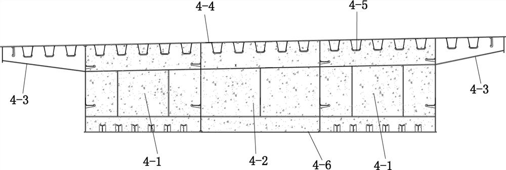
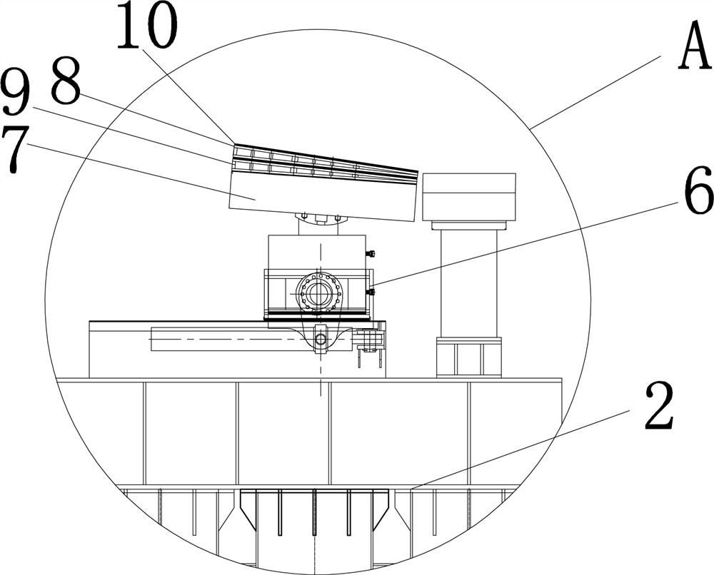
[0091] Firstly, a water tank is installed on the steel box girder 4 close to the end abutment side, and enough water is injected as a counterweight, and the hoisting lug plate at the end of the steel box girder 4 pushed to the design position and the supporting bracket 1 are pre-installed. Buried round steel or other fixtures for anchoring;

[0092] Second, the counterweight is directly placed in one or more steel box girders 4 that are finally assembled, and the hoisting lugs at the end of the steel box girder 4 after being pushed to the design position and the round steel or other pre-embedded support brackets Fixtures are anchored.

[0093] In the present invention, buckle towers and corresponding tension cables 12 are generally installed on the steel box girder 4 corresponding to the central position of the main pier, and the tension cables 12 act on the push-out end of the assembled steel box girder 4 until it reaches the design elevation , one side or both sides of the ...


PUM


Abstract

The invention relates to a large-span variable-cross-section steel box girder incremental launching construction method which is applied to large-span variable-cross-section bridge construction. A supporting support, a pushing support and an assembling support are arranged, the variable-cross-section steel box girder is sequentially arranged on the pushing support and / or the assembling support on the two banks of the water channel after being manufactured, assembling is conducted, the relative position of the steel box girder and the pushing support is adjusted, and pushing is conducted towards the center of the water channel; and after the steel box girder reaches the preset position, posture adjustment, anchoring, closure and welding are conducted, the steel box girder falls on the supporting bracket, and construction is completed. The advantages of high tensile strength, high elastic modulus, high material utilization efficiency, good bearing capacity and no redundant components of the steel box girder are fully utilized, the dead weight is small, and the manufacturing cost is low; the bridge body meets the large-span variable cross-section design requirement and meets the design standard, the structural reliability is high, and water channel navigation is not affected in the construction process; the construction cost is low, the safety coefficient is high, the erection efficiency is high and the construction period is short; the purpose of increasing the height of the bridge arch is achieved, and more complex and changeable navigation requirements are met.

Description

technical field [0001] The invention relates to the technical field of bridges, in particular to a jacking construction method for a large-span variable-section steel box girder. Background technique [0002] In the construction of crossing railways, highways or urban roads, steel box girders are widely used. Steel box girders are also called steel plate box girders. The advantages of steel box girders include: [0003] (1) High tensile strength, high elastic modulus, high material utilization efficiency, good bearing capacity, and no redundant components; [0004] (2) The structure has small weight and low cost; [0005] (3) The structure has high reliability, low construction cost, high erection efficiency and short construction period. [0006] In the prior art, steel box girders have been conveniently used in bridge construction. Through construction without supports, they can cross railways, expressways, and urban intersections without obstacles. [0007] However, t...

Claims


Application Information

Patent Timeline
Patent Type & Authority Applications(China)
IPC IPC(8): E01D21/06E01D2/04
CPCE01D21/06E01D2/04
Inventor 舒育正刘慧丽姜锡东何斌苑青海金华峰刘德龙郑健李佳佳陈喆
Owner ZHEJIANG COMM CONSTR GRP CO LTD
Learn More