Flexible traction power supply system and protection method

A traction power supply system, flexible technology, applied in the direction of power lines, multi-phase network asymmetry reduction, harmonic reduction devices, etc., can solve problems such as low power quality and poor power supply capacity, so as to improve power supply capacity and reliability of power supply performance, avoiding the effect of failure rate

Active Publication Date: 2022-04-29
SOUTHWEST JIAOTONG UNIV
View PDF25 Cites 0 Cited by
  • Summary
  • Abstract
  • Description
  • Claims
  • Application Information

AI Technical Summary

Problems solved by technology

[0002] At present, the traction power supply system for electrified railways in the world basically adopts a three-phase-two-phase power supply mode. The traction transformer in the substation takes power from the three-phase power grid and steps it down, and then divides it into two power supply arms to output power for the traction network. , because the voltage phase, amplitude and frequency of the power supply arms are difficult to be completely consistent, so the electric phase separation needs to be set between the power supply arms, but this kind of traction power supply system has the problems of low power quality and poor power supply capacity
[0003] Therefore, how to reduce or even cancel the electric phase splitting device in the traditional railway traction power supply system and solve the problems of low power quality and poor power supply capacity, and how to improve the reliability of the power supply of the flexible traction power supply system and provide it with suitable The comprehensive protection method is a technical problem to be solved by those skilled in the art

Method used


Image

  • Flexible traction power supply system and protection method
  • Flexible traction power supply system and protection method
  • Flexible traction power supply system and protection method

Examples


Embodiment Construction

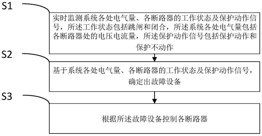
[0058] The following will clearly and completely describe the technical solutions in the embodiments of the application with reference to the drawings in the embodiments of the application. Apparently, the described embodiments are only some of the embodiments of the application, not all of them. Based on the embodiments in this application, all other embodiments obtained by persons of ordinary skill in the art without creative efforts fall within the protection scope of this application.

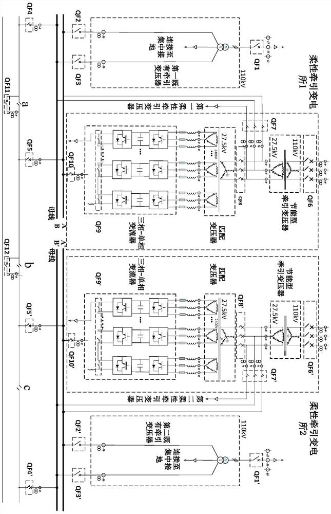
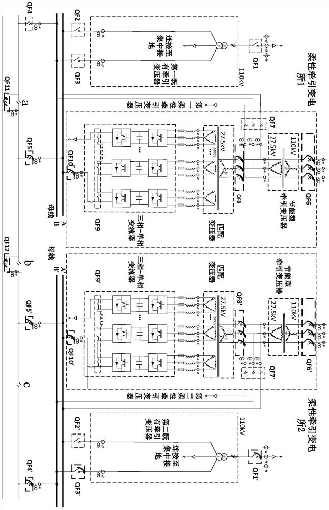
[0059] This application proposes a flexible traction power supply system, such as figure 1 Shown is a schematic structural diagram of a flexible traction power supply system proposed in the embodiment of this application, including:

[0060] The first flexible traction transformer, the first flexible traction transformer includes a circuit breaker QF6, a first energy-saving traction transformer, a circuit breaker QF8, a first matching transformer, a first three-phase-single-phase converter ...


PUM


Abstract

The invention discloses a flexible traction power supply system and a protection method, and the system comprises a first flexible traction transformer, a first existing traction transformer, a second flexible traction transformer, and a second existing traction transformer. The first existing traction transformer, the first flexible traction transformer, the second flexible traction transformer and the second existing traction transformer are sequentially arranged and connected to a bus through corresponding circuit breakers, the system further comprises a circuit breaker QF4, a circuit breaker QF5, a circuit breaker QF5 'and a circuit breaker QF4', the circuit breaker QF4 and the circuit breaker QF5 are located on the two sides of an electric split phase a respectively, and the circuit breaker QF5 and the circuit breaker QF5 'are located on the two sides of the electric split phase a respectively. The circuit breaker QF5 and the circuit breaker QF5'are located on the two sides of the electric split-phase b respectively, and the circuit breaker QF5 'and the circuit breaker QF4' are located on the two sides of the electric split-phase c respectively, so that through power supply of power supply arms on the two sides of the electric split-phase is achieved, the electric energy quality problems of reactive power, negative sequence, harmonic waves and the like in an existing traction power supply system are solved, and the power supply capacity is improved.

Description

technical field [0001] The invention belongs to the technical field of traction power supply, and in particular relates to a flexible traction power supply system and a protection method. Background technique [0002] At present, the traction power supply system for electrified railways in the world basically adopts a three-phase-two-phase power supply mode. The traction transformer in the substation takes power from the three-phase power grid and steps it down, and then divides it into two power supply arms to output power for the traction network. , because the voltage phase, amplitude and frequency of the power supply arms are difficult to be completely consistent, so the electric phase separation needs to be set between the power supply arms, but this kind of traction power supply system has the problems of low power quality and poor power supply capacity. [0003] Therefore, how to reduce or even cancel the electric phase splitting device in the traditional railway trac...

Claims


Application Information

Patent Timeline
Patent Type & Authority Applications(China)
IPC IPC(8): B60M3/00
CPCB60M3/00Y02E40/50
Inventor 何晓琼黄通跃韩鹏程曾理刘育阳韩正庆高仕斌
Owner SOUTHWEST JIAOTONG UNIV
Why Eureka
Try Eureka