
Online insulation tester

An insulation tester and tester technology, applied in instruments, measuring devices, measuring electrical variables, etc., can solve the problems of inability to see the coil with the naked eye, broken coils, invisible coils, etc.

Inactive Publication Date: 2022-04-26
深圳恒越机电设备有限公司
View PDF0 Cites 0 Cited by
  • Summary
  • Abstract
  • Description
  • Claims
  • Application Information

AI Technical Summary

Problems solved by technology

[0002] Insulation testing is very common in electrical and electronic products. Inductors are commonly used components in electrical and electronic products. During the production process of inductance, the inductance value, resistance, and Q value are used to ensure the quality. In order to improve the stability of the quality, of course some will have Other tests, especially the one-piece inductor, during the die-casting process of the one-piece inductor, the coil may be damaged and so on, and the formed one-piece inductor cannot see the coil from the appearance, and the condition of the coil cannot be checked with the naked eye

Method used


Image

  • Online insulation tester
  • Online insulation tester
  • Online insulation tester

Examples


Embodiment 1

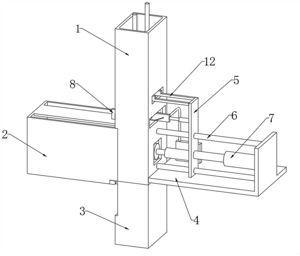
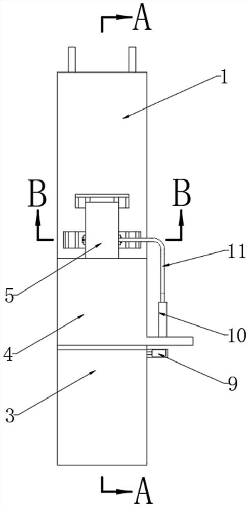
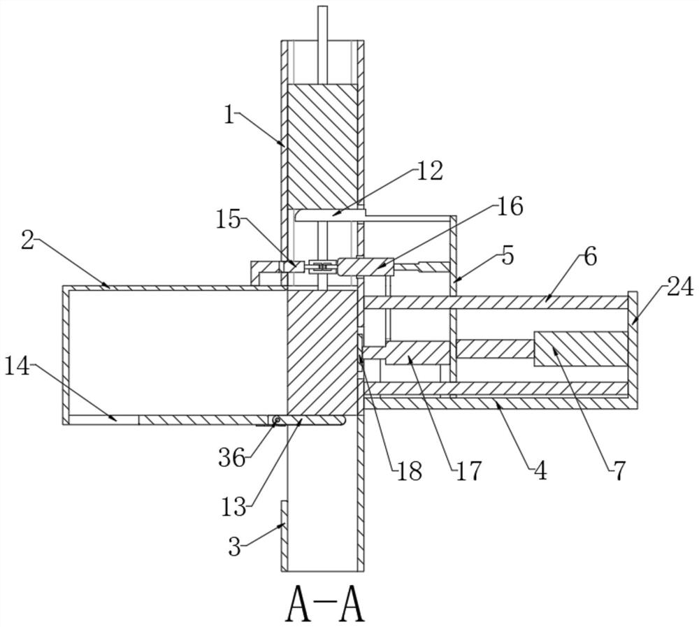
[0039] The control mechanism includes a second mounting block 16 that is slidably connected to the second mounting plate 5. The second mounting block 16 can enter the inside of the feed pipe 1. The outer wall of the second mounting block 16 is hinged with two first transmission rods 22. The ends of each first transmission rod 22 are hinged with a third mounting block 20, the outer walls of the two third mounting blocks 20 are hinged with a second transmission rod 23, and the two second transmission rods 23 are jointly hinged with a first mounting block 20. Mounting block 15, the first mounting block 15, the second mounting block 16, the third mounting block 20, the first transmission rod 22 and the second transmission rod 23 form a four-bar linkage mechanism, and the two third mounting blocks 20 face each other The outer walls of each are fixedly connected with a first transmission patch 21, and the two first transmission patches 21 are respectively electrically connected to th...

Embodiment 2

[0047] The control mechanism includes a mounting seat 25 fixedly connected to the outer wall of the second mounting plate 5, the bottom of the mounting seat 25 is provided with a first chute 34, and the inner wall of the first chute 34 is slidably connected with a first slide block 28, the first slide The bottom of the block 28 is fixedly connected with a long board 29, and the bottom of the long board 29 is fixedly connected with two second transmission patches 30, and the two second transmission patches 30 are respectively electrically connected with two transmission lines 11, and also includes driving two The second transmission patch 30 is downwardly close to the pulling mechanism at the top of the pin of the inductance to be detected, and further includes a driving mechanism for displacing the third mounting board 24 to the top of the pin of the inductance to be detected.

[0048] Such as Figures 6 to 8 As shown, when the inductance enters the inner bottom of the feeding...


PUM


Abstract

An online insulation tester disclosed by the present invention comprises a feeding pipeline, the outer wall of the feeding pipeline is fixedly connected with a first mounting plate, the first mounting plate is provided with a tester, the tester is electrically connected with two transmission lines, and the inner wall of the feeding pipeline allows an inductor to be detected to slide downwards to the bottom of the feeding pipeline. A second mounting plate is fixedly connected to the top of the first mounting plate, a control mechanism for connecting pins of an inductor to be detected is arranged on the outer wall, close to the feeding pipeline, of the second mounting plate, and the control mechanism can control an interlayer detection circuit which is electrically connected between the two transmission lines and the two pins. According to the inductor conveying device, interlayer detection can be carried out on inductors, and meanwhile the detected inductors can be conveyed in a classified mode.

Description

technical field [0001] The invention relates to the technical field of insulation testing, in particular to an online insulation testing instrument. Background technique [0002] Insulation testing is very common in electrical and electronic products. Inductors are commonly used components in electrical and electronic products. During the production process of inductance, the inductance value, resistance, and Q value are used to ensure the quality. In order to improve the stability of the quality, of course some will have For other tests, especially the one-piece inductor, the coil may be damaged during the die-casting process of the one-piece inductor, but the coil cannot be seen from the appearance of the molded one-piece inductor, and the condition of the coil cannot be checked with the naked eye. [0003] Therefore, it is necessary to measure the inductance between layers to ensure the quality of the inductance. Contents of the invention [0004] The object of the pre...

Claims


Application Information

Patent Timeline
Patent Type & Authority Applications(China)
IPC IPC(8): G01R19/165
CPCG01R19/165
Inventor 吉明阳陈加阳高超杨天贵
Owner 深圳恒越机电设备有限公司
Learn More