
Spring return type rope-driven mechanical arm

A mechanical arm and recovery technology, which is applied in the field of spring-returning rope-driven mechanical arms, can solve the problems of lower energy utilization, high power of the mechanical arm, and large mass of the boom part of the mechanical arm, so as to improve energy utilization. , Reduce power consumption, reduce power effect

Pending Publication Date: 2022-04-26
SHENYANG POLYTECHNIC UNIV +1
View PDF0 Cites 0 Cited by
  • Summary
  • Abstract
  • Description
  • Claims
  • Application Information

AI Technical Summary

Problems solved by technology

This method usually makes the mass of the boom part of the manipulator too large, and the motor, reducer and other devices at the rear joint will become the load driven by the front joint, resulting in relatively high power of the manipulator and reducing the energy utilization rate.
And the mechanical arm is too rigid and lacks flexibility, making it unsuitable for medical, service, family and other occasions with high human-computer interaction

Method used


Image

  • Spring return type rope-driven mechanical arm
  • Spring return type rope-driven mechanical arm
  • Spring return type rope-driven mechanical arm

Examples


Embodiment Construction

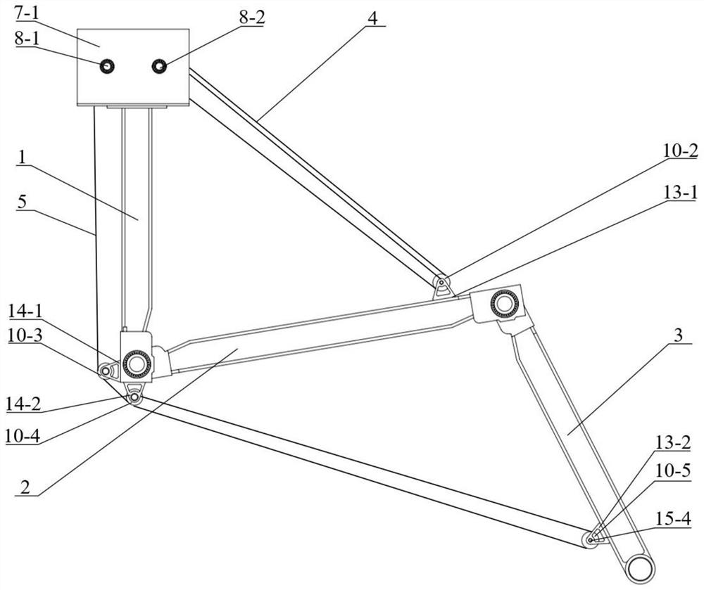
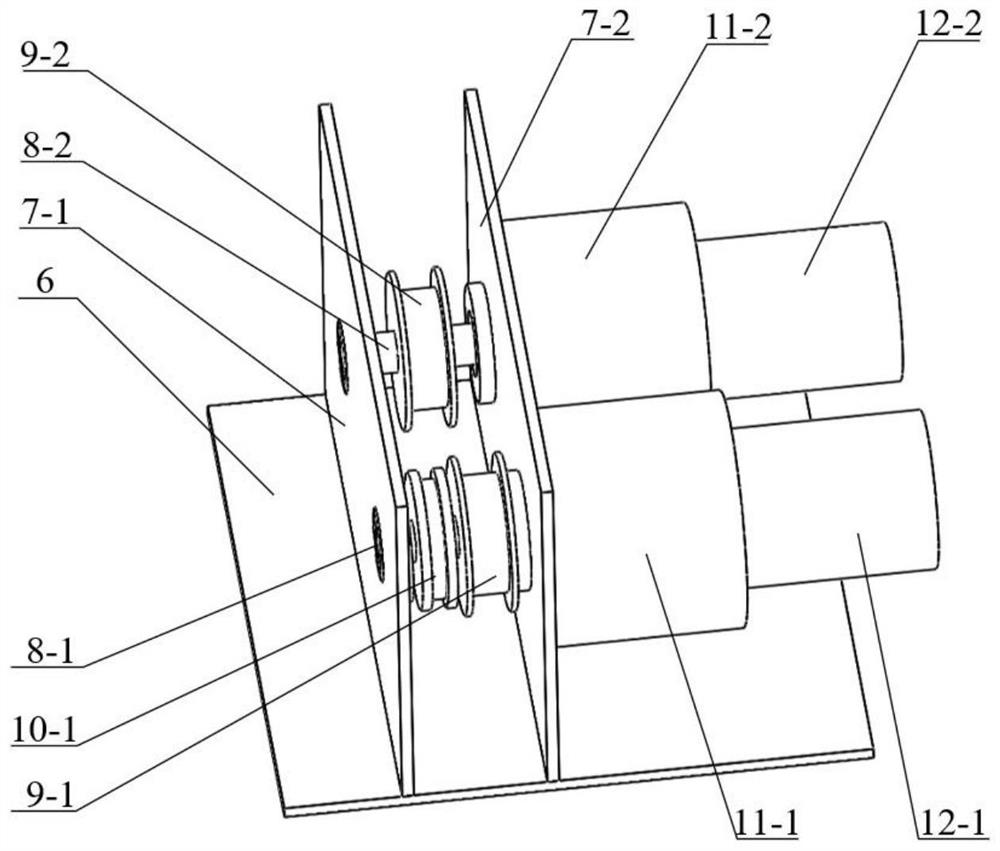
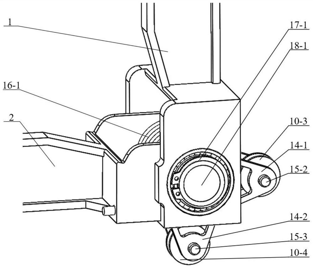
[0017] see Figure 1-4 , the present invention provides a technical solution: a spring return type rope-driven mechanical arm, the mechanical arm is provided with a base support plate 6, a driving mechanism is installed on one side of the base support plate 6, and the base supports The other side of the plate 6 is equipped with the head end of the upper arm 1, the tail end of the upper arm 1 is installed with the head end of the middle arm 2 through the shoulder joint torsion spring 16-1, and the tail end of the middle arm 2 is passed through the elbow joint torsion spring 16-2 installs the head end of the forearm 3; through the setting of the shoulder joint torsion spring 16-1 and the elbow joint torsion spring 16-2, the spring can be compressed and released when the shoulder joint rotates. At the same time, the upper arm 1 and the middle arm 2 are axially connected through the shoulder joint shaft 18-1, and the axial position is limited by the shoulder joint shaft spring 17-...


PUM


Abstract

The invention discloses a spring return type rope-driven mechanical arm which is provided with a base supporting plate, a driving mechanism is installed on one side of the base supporting plate, the head end of an upper arm is installed on the other side of the base supporting plate, and the tail end of the upper arm is installed at the head end of a middle arm through a shoulder joint torsion spring. The tail end of the middle arm is installed at the head end of the small arm through an elbow joint torsion spring. According to the mechanical arm, the mechanical arm joint is driven by the spring return type rope, the tail end of the driving rope is fixed to the mechanical arm rod, the distance between the driving rope and the joint is far, and the force arm acted by the rope is large. The rope tension is much smaller under the condition of the same load, so that the power required by the driving motor can be greatly reduced, the power consumption is reduced, and the utilization rate of energy is further improved.

Description

technical field [0001] The invention relates to the technical field of rope-driven manipulators, in particular to a spring return type rope-driven manipulator. Background technique [0002] With the development of science and technology, industrial production is becoming increasingly automated, and robotic arms have been used more and more widely. The traditional robotic arm uses motors, reducers and other drive units directly placed at the joints to drive the rotation of the joints, which has the advantages of high precision, fast speed, and high efficiency, and has been widely used in manufacturing, assembly, logistics and other fields. This method usually makes the mass of the boom part of the manipulator too large, and the motor, reducer and other devices at the rear joint will become the load driven by the front joint, resulting in relatively high power of the manipulator and reducing the energy utilization rate. Moreover, the rigidity of the mechanical arm is too larg...

Claims


Application Information

Patent Timeline
Patent Type & Authority Applications(China)
IPC IPC(8): B25J9/10B25J9/04
CPCB25J9/104B25J9/04
Inventor 孙凤茅冒徐方超张明金俊杰马天宇张伟伟姜生元李鹏刘雅芳杨旭
Owner SHENYANG POLYTECHNIC UNIV
Learn More