
Glue injection and edge sealing process for hollow plastic template

A plastic formwork and glue injection technology, which is applied in the direction of coating and liquid coating device on the surface, can solve the problems that the formwork is easy to stick to sediment, increase the weight of the formwork, and affect the use of the formwork, so as to achieve good edge sealing effect and reduce The degree of damage, the effect of easy cleaning

Pending Publication Date: 2022-04-26
广东皓强科技有限公司
View PDF10 Cites 0 Cited by
  • Summary
  • Abstract
  • Description
  • Claims
  • Application Information

AI Technical Summary

Problems solved by technology

The consequences caused by the through hole of the core layer entering the cement mortar and being tightly blocked by the cement mortar are as follows: first, the cleaning workload after the use of the formwork is increased; second, the weight of the formwork is increased, which affects the turnover of the formwork; The size of the template is deviated from the original size due to the expansion of the original hole in the hole, and the unstable size of the template seriously affects the subsequent use of the template
[0003] Traditional dispensing materials are directly used for glue injection and edge sealing. After drying and curing, they maintain high viscosity and last for a long time. After edge sealing, the formwork is easy to stick to common light building materials such as sand and dust on construction sites, which affects the use of formwork.
Secondly, due to the high viscosity of traditional dispensing materials, it is not easy to scrape flat after the glue gun is released, which affects the flatness of the side surface of the template after edge sealing
Finally, the traditional dispensing material has no elasticity or general elasticity after drying and curing. After using this material for edge sealing, it cannot give better protection to the hollow plastic formwork

Method used


Image

  • Glue injection and edge sealing process for hollow plastic template
  • Glue injection and edge sealing process for hollow plastic template
  • Glue injection and edge sealing process for hollow plastic template

Examples


Embodiment Construction

[0032] The following will clearly and completely describe the technical solutions in the embodiments of the present invention with reference to the accompanying drawings in the embodiments of the present invention. Obviously, the described embodiments are only some, not all, embodiments of the present invention. Based on the embodiments of the present invention, all other embodiments obtained by persons of ordinary skill in the art without creative efforts fall within the protection scope of the present invention.

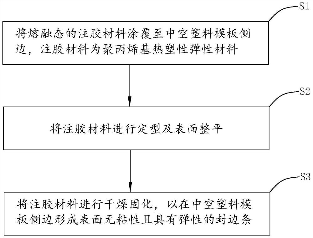
[0033] An embodiment of the present invention provides a hollow plastic template injection glue edge sealing process, including the following steps:

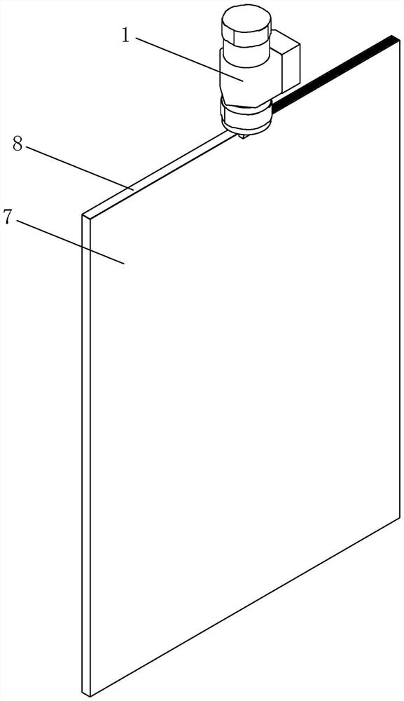
[0034] S1. Apply the molten glue injection material to the side of the hollow plastic template 7, the glue injection material is a polypropylene-based thermoplastic elastic material;

[0035] S2, shaping and leveling the injection material;

[0036] S3. Drying and curing the glue injection material to form an elasti...


PUM


Abstract

The invention relates to the technical field of hollow plastic template processing, and particularly provides a hollow plastic template glue injection and edge sealing process, which comprises the following steps: firstly, coating a molten glue injection material to the side edge of a hollow plastic template, and then shaping and leveling the surface of the glue injection material, according to the hollow plastic formwork, the elastic edge sealing strip with the non-sticky surface is formed on the side edge of the hollow plastic formwork after drying and curing, and particulate matter impurities such as cement and light silt are effectively prevented from blocking through holes of a core layer, and the polypropylene-based thermoplastic elastic material which is appropriate in viscosity, non-sticky after drying and curing and elastic is selected as a glue injection material; buffer protection can be provided for the four side edges of the hollow plastic formwork, and the damage degree caused by falling and collision of the hollow plastic formwork in the disassembling, assembling and carrying processes is reduced.

Description

technical field [0001] The invention relates to the technical field of hollow plastic formwork processing, in particular to a glue injection and edge sealing process for hollow plastic formwork. Background technique [0002] Hollow plastic formwork has the advantages of good molding quality, light weight, and many turnover times, and is widely used in the construction formwork industry. Compared with the aluminum formwork, the reason why the hollow plastic formwork is lighter on one side is not only the material of the plastic formwork itself, but also an important factor is that its core layer is a unique hollow structure that runs through the length of the formwork (hereinafter referred to as the core layer) through hole). However, the through-hole structure of the core layer also has its disadvantages. For example, during the use of the formwork, cement mortar is easy to enter the through-hole of the core layer, and what is more, the through-hole of the core layer will b...

Claims


Application Information

Patent Timeline
IPC IPC(8): B05C5/02B05C11/02B05C9/14C08L23/12C08L23/16C08L23/08C08L53/02C08K3/26C08K5/14
CPCB05C5/0212B05C11/023B05C9/14C08L23/12C08K2003/265C08L23/16C08L23/0815C08L53/02C08K3/26C08K5/14
Inventor 陈艳萍段辉蒲颖饶再清冯盼盼林沐钦李晓拓
Owner 广东皓强科技有限公司
Learn More