Water gate pier spraying device for water conservancy project

A water conservancy project and spraying device technology, which is applied in spraying devices, liquid spraying devices, cleaning methods using tools, etc., can solve problems such as low work efficiency and paint precipitation, and achieve the effect of avoiding dragging, avoiding precipitation, and improving adhesion effect

Inactive Publication Date: 2022-04-26
张冰
View PDF0 Cites 1 Cited by
  • Summary
  • Abstract
  • Description
  • Claims
  • Application Information

AI Technical Summary

Problems solved by technology

[0004] The purpose of the present invention is to solve the problem that the spraying method in the prior art still adopts manual operation, so that the work efficiency is low, and if the spraying time is too long, it will easily lead to the precipitation of the paint, and the dust and impurities on the surface of the gate pier will affect the quality of the paint after spraying. The shortcomings of the effect, and proposed a water sluice pier spraying device for water conservancy projects

Method used


Image

  • Water gate pier spraying device for water conservancy project
  • Water gate pier spraying device for water conservancy project
  • Water gate pier spraying device for water conservancy project

Examples


Embodiment 1

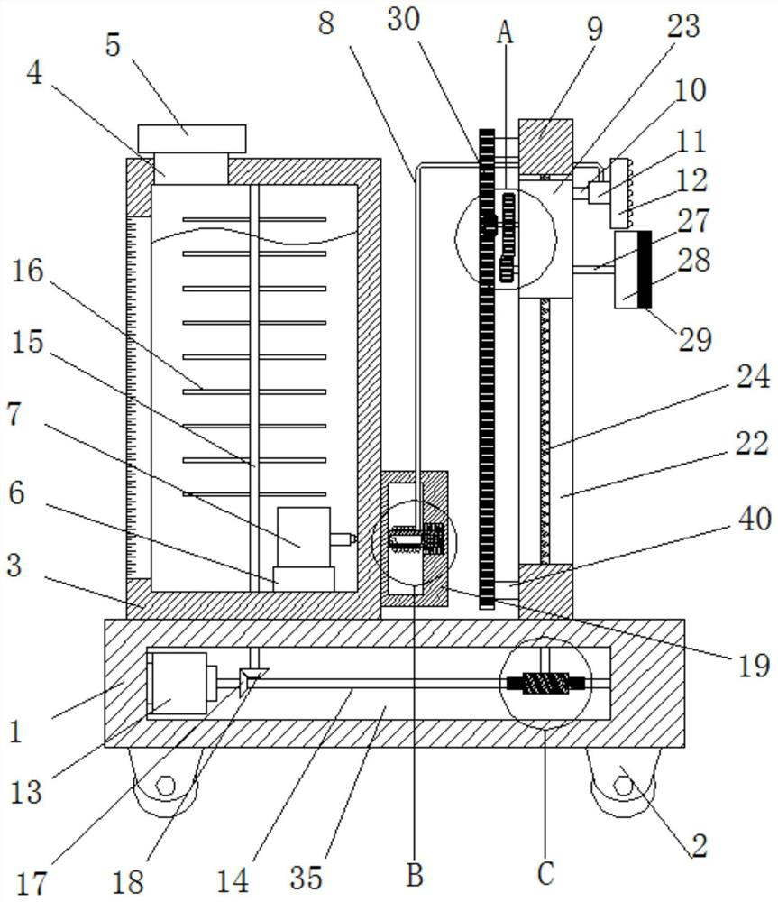
[0028] refer to Figure 1-5 , a water gate pier spraying device for water conservancy projects, comprising a base 1, a plurality of universal wheels 2 are arranged on the bottom of the base 1, a paint box 3 is arranged on the top of the base 1, and a feed pipe 4 is arranged on the top of the paint box 3 , the feed pipe 4 is provided with a sealing cover 5, the paint tank 3 is provided with a connecting seat 6, and the connecting seat 6 is provided with a booster pump 7, and the right side of the paint tank 3 is provided with a pipeline winding mechanism, and the pipeline winding mechanism A delivery leather tube 8 is wound on the top, and one end of the delivery leather tube 8 is rotatably connected to the output port of the booster pump 7. The top of the base 1 is fixedly connected with a vertical column 9 by welding, and the vertical column 9 is provided with a reciprocating displacement mechanism. Displacement mechanism is provided with connecting rod 10, and connecting rod...

Embodiment 2

[0039] The difference from Embodiment 1 is that it includes a base 1, a plurality of universal wheels 2 are arranged on the bottom of the base 1, a paint box 3 is arranged on the top of the base 1, a scale bar is arranged on the left side of the paint box 3, and the paint The top of the tank 3 is provided with a feed pipe 4, the feed pipe 4 is provided with a sealing cover 5, the paint tank 3 is provided with a connection seat 6, a booster pump 7 is provided on the connection seat 6, and the right side of the paint tank 3 is provided with a There is a pipeline winding mechanism, on which a delivery leather tube 8 is wound, and one end of the delivery leather tube 8 is rotatably connected to the output port of the booster pump 7, and the top of the base 1 is fixedly connected with a vertical column 9, and the vertical column 9 A reciprocal displacement mechanism is arranged on the upper surface, and a connecting rod 10 is arranged on the reciprocal displacement mechanism. The co...


PUM


Abstract

The invention belongs to the field of spraying devices, particularly relates to a water gate pier spraying device for a water conservancy project, and aims to solve the problems that an existing spraying mode still adopts manual operation, so that the working efficiency is low, the phenomenon of precipitation of paint is easily caused by too long spraying time, and dust, impurities and the like on the surface of a gate pier influence the effect after spraying. According to the technical scheme, the spraying device comprises a base, a plurality of universal wheels are arranged at the bottom of the base, a coating box is arranged at the top of the base, a feeding pipe is arranged at the top of the coating box, a sealing cover is arranged on the feeding pipe, and a connecting base is arranged in the coating box. The device is simple in structure and convenient to operate, impurities, dust and the like on the gate pier can be removed in time, the adhesion effect of paint and the final spraying quality are effectively improved, in addition, the phenomenon that the paint precipitates can be effectively avoided, and a conveying leather hose can be effectively wound and prevented from being dragged and damaged.

Description

technical field [0001] The invention relates to the technical field of spraying devices, in particular to a spraying device for sluice piers of water conservancy projects. Background technique [0002] In the lock chamber, it is used to support the gate, separate the gate hole, and connect the two sides of the pier. The side pier connecting the two banks is called the side pier, and the middle part is called the middle pier. Under normal circumstances, the gate pier not only supports the gate, but also supports the parapet and bridge; In order to reduce the span of the arc gate, another gate pier can also be set in the middle of the gate hole, but it is very unfavorable for overcurrent and discharge of floating objects, and it is rarely used in engineering practice. For plane gates, gate slots are set on the side of the pier; The gate and the pier side are provided with corbels to support the gate. The profile of the gate pier needs to make the water flow through the gate sm...

Claims


Application Information

Patent Timeline
Patent Type & Authority Applications(China)
IPC IPC(8): B05B9/04B05B13/04B05B15/25B05B15/00B08B1/04B08B1/00
CPCB05B9/0403B05B13/041B05B15/25B05B15/00B08B1/32B08B1/12
Inventor 张冰
Owner 张冰
Why Eureka
Try Eureka