
Assembly structure of wire harness, electronic equipment and atmosphere lamp

A technology of assembly structure and wiring harness, applied in the direction of electrical components, etc.

Pending Publication Date: 2022-04-22
当趣网络科技(杭州)有限公司
View PDF0 Cites 0 Cited by
  • Summary
  • Abstract
  • Description
  • Claims
  • Application Information

AI Technical Summary

Problems solved by technology

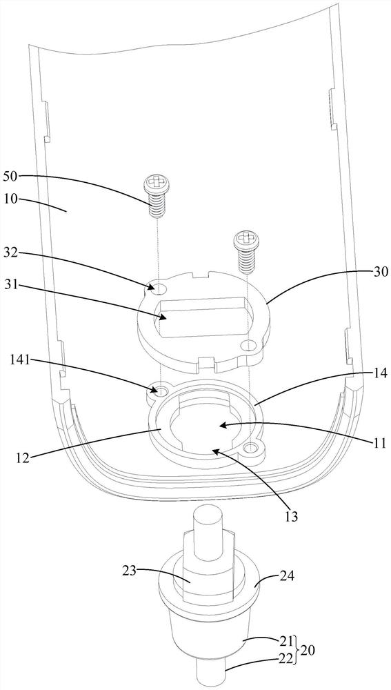
[0003] The main purpose of the present invention is to propose a wire harness assembly structure, aiming to solve the technical problem of how to improve the fixing strength of the wire harness at the wiring hole of the equipment housing

Method used


Image

  • Assembly structure of wire harness, electronic equipment and atmosphere lamp
  • Assembly structure of wire harness, electronic equipment and atmosphere lamp
  • Assembly structure of wire harness, electronic equipment and atmosphere lamp

Examples


Embodiment Construction

[0036] The following will clearly and completely describe the technical solutions in the embodiments of the present invention with reference to the accompanying drawings in the embodiments of the present invention. Obviously, the described embodiments are only part of the embodiments of the present invention, not all of them. Based on the embodiments of the present invention, all other embodiments obtained by persons of ordinary skill in the art without creative efforts fall within the protection scope of the present invention.

[0037] It should be noted that if there is a directional indication (such as up, down, left, right, front, back...) in the embodiment of the present invention, the directional indication is only used to explain the position in a certain posture (as shown in the accompanying drawing). If the specific posture changes, the directional indication will also change accordingly.

[0038] In addition, if there are descriptions involving "first", "second" and ...


PUM


Abstract

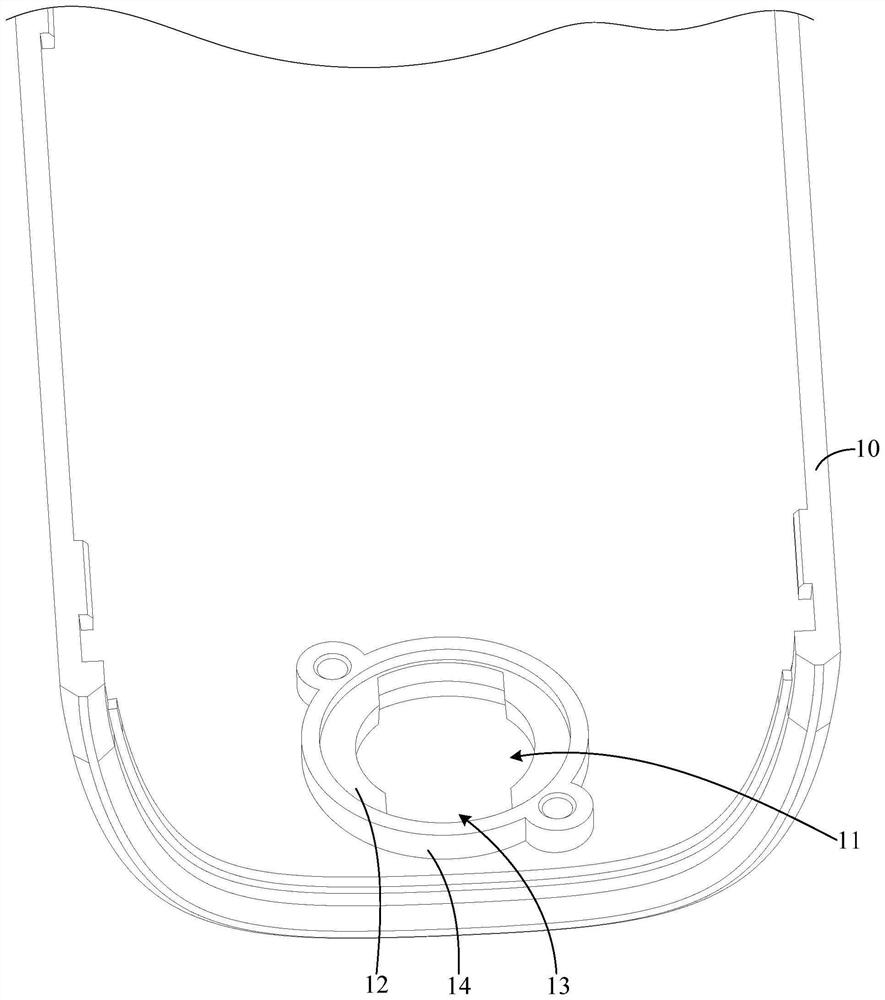
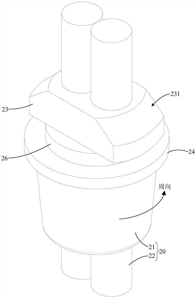
The invention discloses an assembly structure of a wire harness, electronic equipment and an atmosphere lamp, and the assembly structure of the wire harness comprises the wire harness which comprises a wire buckle and a wire body which fixedly penetrates through the wire buckle; a limiting boss and at least two clamping bosses are formed on the peripheral wall of the wire buckle in a protruding mode in the radial direction, the clamping bosses are arranged at intervals in the circumferential direction of the wire body, and clamping grooves are formed between the clamping bosses and the limiting boss; the equipment shell is provided with a wiring hole for the wire harness to penetrate through, the hole wall of the wiring hole is provided with at least two stopping parts in a protruding mode, the stopping parts extend in the circumferential direction of the wiring hole and are arranged in the circumferential direction of the wiring hole at intervals, and the stopping parts are located in the clamping grooves so that the wire harness and the equipment shell can be assembled; the adjacent stopping parts form through grooves used for penetrating through the clamping bosses in interval areas in the circumferential direction, the stopping parts are screwed into the clamping grooves in the wire buckles, and the stopping parts are used for limiting the limiting bosses to penetrate through the wiring holes. The assembly structure of the wire harness can improve the fixing effect of the wire harness at the wiring hole of the equipment shell.

Description

technical field [0001] The invention relates to the technical field of electronic equipment, in particular to an assembly structure of a wire harness, electronic equipment and an ambient light. Background technique [0002] After the conductive wire harness of the electronic device is connected to the device housing, in order to prevent the inner and outer core wires of the wire from being torn off when the wire is pulled, it is necessary to make the conductive wire harness form a fixed fit relationship with the device housing. In the related art, the fixed fit of the conductive wire harness at the wiring hole of the equipment casing is realized by means of a wire crimping member. This fixing method has poor stability, which makes the conductive wire bundle easy to loosen under force. Contents of the invention [0003] The main purpose of the present invention is to propose an assembly structure of a wire harness, aiming at solving the technical problem of how to improve t...

Claims


Application Information

Patent Timeline
IPC IPC(8): H02G3/02H02G3/04
CPCH02G3/02H02G3/045
Inventor 金凌琳李志诸飞灵
Owner 当趣网络科技(杭州)有限公司
Learn More