Backlight module and display equipment

A backlight module and display panel technology, applied in the direction of light guides, optics, optical components, etc., can solve the problem that the backlight module cannot better realize automatic assembly, and achieve a good supporting effect

Pending Publication Date: 2022-04-22
CHONGQING HKC OPTOELECTRONICS TECH CO LTD +1
View PDF0 Cites 2 Cited by
  • Summary
  • Abstract
  • Description
  • Claims
  • Application Information

AI Technical Summary

Problems solved by technology

[0003] The main purpose of the present invention is to propose a backlight module, which aims to improve the problem that the backlight module cannot better realize automatic assembly during the assembly process

Method used


Image

  • Backlight module and display equipment
  • Backlight module and display equipment
  • Backlight module and display equipment

Examples


Embodiment Construction

[0024] The following will be combined with the accompanying drawings in the embodiments of the present invention, the technical solution in the embodiments of the present invention will be described clearly and completely, it is clear that the embodiments described are only part of the embodiments of the present invention, and not all embodiments. Based on embodiments in the present invention, all other embodiments obtained by those of ordinary skill in the art without making creative labor, are within the scope of protection of the present invention.

[0025] It should be noted that, if there are directivity indications involved in the present invention (such as up, down, left, right, front, back...), the directionality indication is only used to explain the relative position relationship between the various components under a particular attitude (as shown in the drawings), the movement, etc., if the particular attitude changes, the directionality indication also changes accordin...


PUM


Abstract

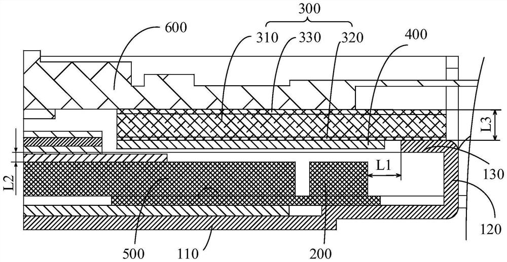
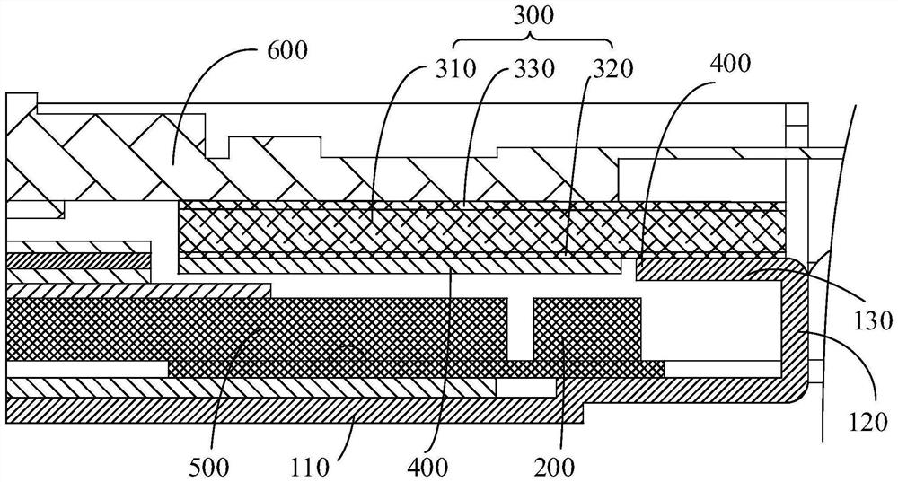
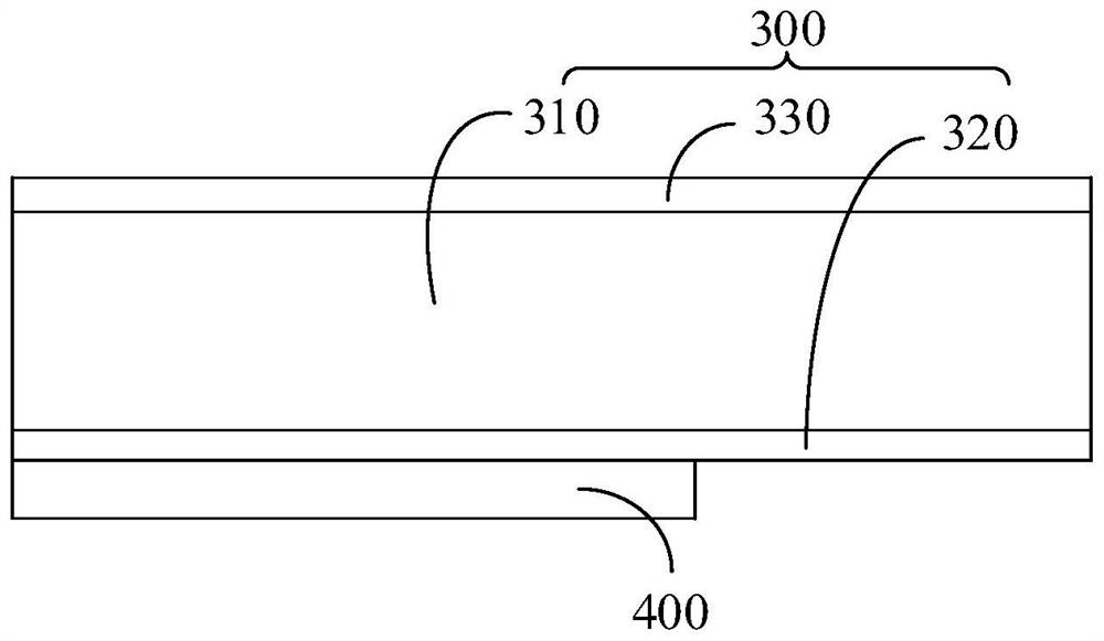
The invention discloses a backlight module and display equipment. The backlight module comprises a back plate, a light bar, a supporting structure and a reflecting part, the back plate comprises a bottom plate and a side plate, the side plate is connected with the bottom plate, and a flange is formed; the light bar is arranged on the bottom plate, and the projection of at least part of the light bar on the bottom plate does not coincide with the projection of the flange on the bottom plate; the supporting structure is arranged on the side, away from the bottom plate, of the turned-over edge, extends to the position above the lamp strip and is used for supporting the display panel. The reflecting piece is connected to the side, facing the lamp strip, of the supporting structure. The part, where the projection of the light bar on the bottom plate does not coincide with the projection of the flanging on the bottom plate, is defined as an exposed part, and at least part of the reflecting piece is arranged above the exposed part. According to the technical scheme, the reflecting part, the supporting structure and the light bar are free of more interference in the installation process, and therefore automation can be conveniently achieved in the assembly process of the whole backlight module.

Description

Technical field [0001] The present invention relates to the technical field of display devices, in particular to a backlight module and a display device using the backlight module. Background [0002] In the conventional backlight module design, the backlit base plate is in contact with the light bar, and the reflective tape is set on the side of the back panel facing the bottom plate by flipping out of the flange and the side of the backplane facing the bottom plate, so as to improve the phenomenon of light leakage or particular brightness at the light source of the light bar when the large oblique viewing angle is seen. However, because the reflective tape is set on the lower surface of the backplane, it is necessary to manually paste the reflective adhesive strip and then feed the backplane, making the automatic assembly very inconvenient. Contents of the Invention [0003] The main object of the present invention is to propose a backlight module, aimed at improving the prob...

Claims


Application Information

Patent Timeline
Patent Type & Authority Applications(China)
IPC IPC(8): G09F9/00G02B6/00
CPCG09F9/00G02B6/0088G02B6/009
Inventor 黄皓曹太鑫康报虹
Owner CHONGQING HKC OPTOELECTRONICS TECH CO LTD
Why Eureka
Try Eureka