
Measuring device and measuring method for mechanical parameters

A technology of mechanical parameters and measuring devices, which is applied in the field of mechanical parameter measurement, can solve the problems that the experimental results cannot be eliminated, occupy a large space, and affect the stability of the device, so as to meet the needs of scientific research and teaching practice, easy to operate, and avoid external The effect of disturbance

Active Publication Date: 2022-04-22
XIAMEN UNIV
View PDF10 Cites 0 Cited by
  • Summary
  • Abstract
  • Description
  • Claims
  • Application Information

AI Technical Summary

Problems solved by technology

For example, the optical lever mirror ruler method commonly used in teaching courses not only takes up a large space, but also is difficult to adjust and complicated to operate. At the same time, the operation of manually hanging heavy objects will also have a certain impact on the stability of the device, which will inevitably affect the experimental results. Eliminated errors

Method used


Image

  • Measuring device and measuring method for mechanical parameters
  • Measuring device and measuring method for mechanical parameters
  • Measuring device and measuring method for mechanical parameters

Examples


Embodiment 1

[0036] Embodiment 1 provides a measuring device and method for mechanical parameters;

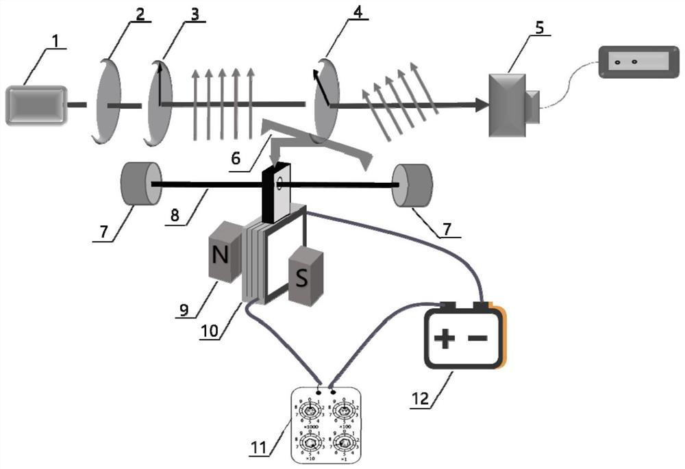
[0037] Such as figure 1 , the measuring device of the mechanical parameter of the present embodiment, comprises steel wire 8 to be measured, fixture 7, the square coil 10 that number of turns is n, the permanent magnet 9 that magnetic induction intensity is B, laser device 1, band-pass filter 2, the first Polarizer 3, second polarizer 4, tripod support 6, optical power meter 5, DC power supply 12 and resistor 11; the laser 1 and bandpass filter 2 provided in this embodiment are both 532nm;

[0038] Wherein the clamp 7 is used to fix the two ends of the steel wire 8 to be tested, and the square coil 10 with the number of turns m is vertically suspended at the midpoint of the steel wire to be tested, and placed in the middle of the two poles of the permanent magnet 9 whose magnetic induction is B. At the magnetic field; 532nm laser 1, 532nm band-pass filter 2, first polarizer 3, and optical ...

Embodiment 2

[0060] Embodiment 2 provides another measuring device for mechanical parameters and a corresponding measuring method; specifically:

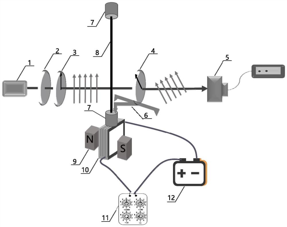
[0061] Such as figure 2 , the structure of the device of this embodiment is the same as that of the first embodiment, the difference is that the laser 1 and the band-pass filter 2 are 488nm, and the material to be measured includes the fiber filament to be measured;

[0062] During specific measurement, the measuring method is the same as the embodiment, the difference is that the two ends of the fiber to be measured are fixed with clamps 7, so that the fiber to be measured is in a vertically suspended tension state, and the coil 10 is vertically suspended on the fiber to be measured. On the collet of the lower end fixture 7; the placement state of the material to be tested is different from that of Embodiment 1, which is also an essential difference.

[0063] When adjusting the current, gradually increase the current every 0.2A. In fact, the ...


PUM


Abstract

The invention provides a measuring device for mechanical parameters. The measuring device comprises a clamp, a coil, a magnet, a light source, an optical filter, a first polaroid, a second polaroid, a tripod, an optical power meter or a spectrograph, a probe of the optical power meter or the spectrograph, a direct-current power supply and a resistor. The clamp is used for fixing the two ends of a to-be-tested material, and the coil is suspended at the midpoint of the horizontally-placed to-be-tested material or suspended at the lower end of the vertically-placed to-be-tested material and is arranged at a uniform magnetic field between the two poles of the magnet; the light source, the optical filter, the first polaroid, the second polaroid and the optical power meter or the spectrograph probe are consistent in height, and light rays emitted by the light source vertically pass through the optical filter, the first polaroid, the second polaroid and the optical power meter or the spectrograph probe in sequence; the second polaroid is fixed on the three-legged support, one tip of the three-legged support is arranged on the clamp, the other two tips of the three-legged support are fixedly arranged on a horizontal plate, and the two ends of the coil wire are connected with the resistor and the direct-current power supply to form a closed loop. The device is simple to operate and accurate in result, and has the advantages of being controllable, easy to adjust, stable, continuous, high in anti-interference performance and the like.

Description

technical field [0001] The invention relates to the field of mechanical parameter measurement, in particular to a measuring device and method for mechanical parameters. Background technique [0002] Deformation is widely used in mechanical measurement, energy conversion, flexible devices and so on. Wearable devices provide new ideas for industries such as medical care, electronics, and analysis and testing. my country's aerospace industry has made a major breakthrough. The flexible solar cell wing was first applied to my country's space station. The panels used a large area of ​​flexible materials that can be retracted, which greatly reduced the mass and improved the carrying capacity of the space station. The determination of deformation-related mechanical parameters is the key to the selection and design of flexible materials, which has important scientific significance and application value. [0003] Young's modulus, modulus of elasticity, and Poisson's ratio are import...

Claims


Application Information

Patent Timeline
Patent Type & Authority Applications(China)
IPC IPC(8): G01L1/04G01B11/16
CPCG01L1/04G01B11/16
Inventor 吴雅苹张纯淼刘伟杰黄佳傲
Owner XIAMEN UNIV
Learn More