Bone screw

A technology of bone screw and screw rod, which is applied in the field of self-drilling and self-tapping bone screws, and can solve problems such as injuries

Pending Publication Date: 2022-04-22
铂泰生医股份有限公司
View PDF10 Cites 0 Cited by
  • Summary
  • Abstract
  • Description
  • Claims
  • Application Information

AI Technical Summary

Problems solved by technology

But this self-drilling self-tapping bone screw has a sharp point, so the point is easy to cause damage to other tissues after passing through the bone

Method used


Image

  • Bone screw
  • Bone screw
  • Bone screw

Examples


Embodiment Construction

[0016] The present invention will be described in detail below in conjunction with the accompanying drawings and embodiments.

[0017] Before the present invention is described in detail, it should be noted that in the following description, similar elements are denoted by the same numerals.

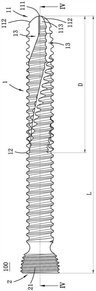
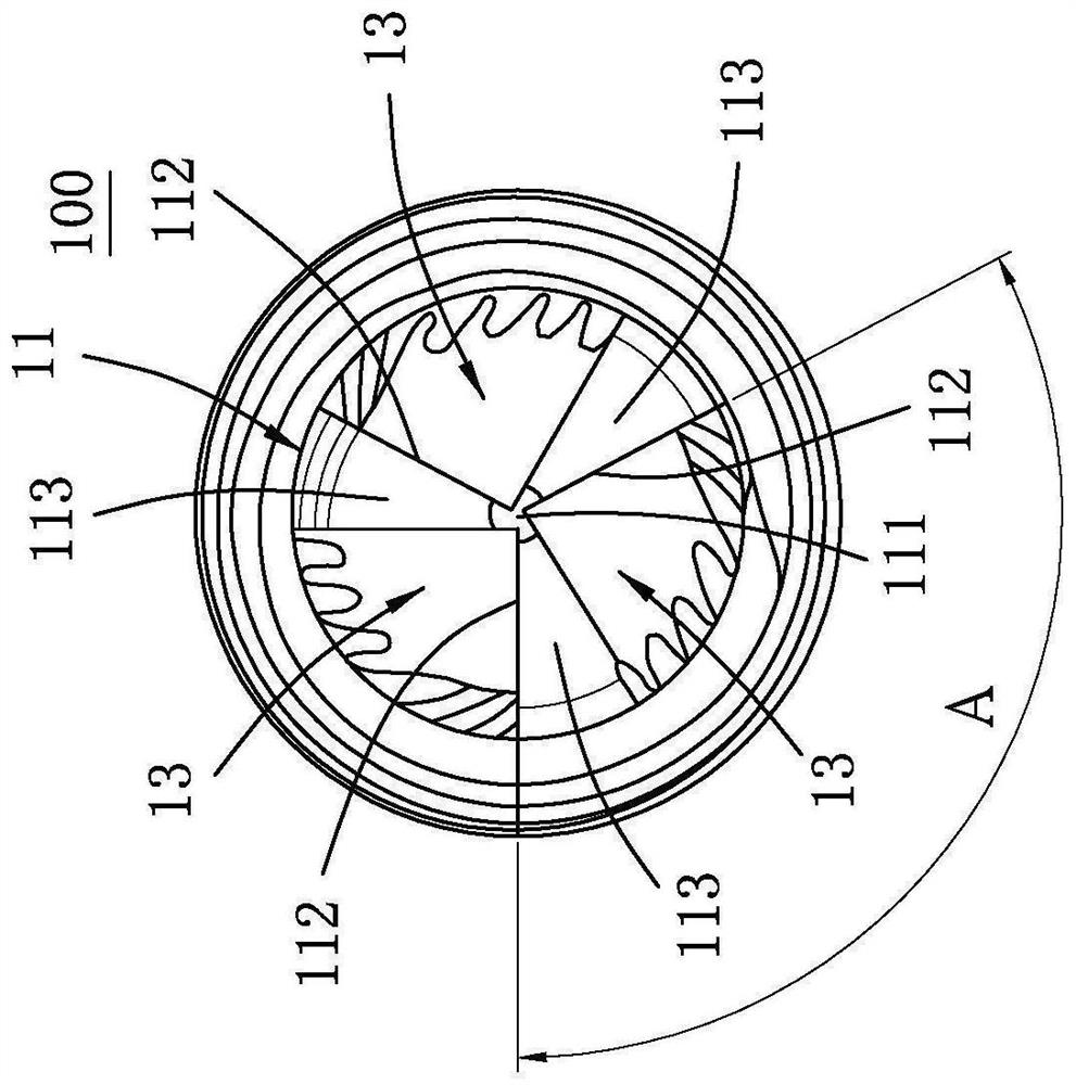
[0018] refer to figure 1 , an embodiment of the bone screw 100 of the present invention, the bone screw 100 is a self-drilling self-tapping bone screw and includes a screw shank 1 and a screw head 2 .

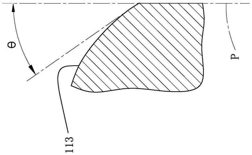
[0019] refer to figure 1 , figure 2 and image 3 , the nail shank 1 includes a tip section 11 and a first thread section 12 formed at one end of the tip section 11 . The tip segment 11 has an end portion 111 , a plurality of cutting edges 112 , and a plurality of relief surfaces 113 . The end portion 111 in this embodiment is a circular arc end face. The cutting edges 112 extend from the end portion 111 and are arranged at equiangular intervals. The number of the cutting edges 112...


PUM


Abstract

A bone screw comprises a screw rod and a screw head. The nail rod comprises a tip section and a first threaded section formed at one end of the tip section, the tip section is provided with an end, a plurality of cutting edges and a plurality of rear tool faces, the cutting edges extend out of the end and are arranged at intervals at equal angles, the rear tool faces are formed on the rear sides of the cutting edges respectively, and the end is an arc end face. A rear oblique angle is defined between the cutting plane of any point on each cutting edge and the corresponding rear tool face, a plurality of chip containing grooves extending from the end to the first thread section are formed in the nail rod, and each chip containing groove is in a spiral shape. The nail head is formed at the end, opposite to the tip end section, of the first threaded section, and the nail head comprises a second threaded section. Therefore, the tip section can play a drilling role. The end part is an arc end surface, so that other tissues can be prevented from being punctured.

Description

technical field [0001] The invention relates to a surgical instrument, in particular to a self-drilling self-tapping bone screw for implanting in bone. Background technique [0002] Conventionally, when a bone plate is to be fixed to a broken bone by a plurality of bone screws, the screw-locking operations of the bone screws need to be performed sequentially. When the screw locking of each bone screw is to be performed, firstly, a guide sleeve is locked on the bone plate, and then a drill bit is passed through the guide sleeve and guided to the bone plate through it. Drill holes. Then measure whether the depth of the hole drilled on the bone meets the requirements. Finally, a self-tapping bone screw is penetrated through the bone plate and locked into the bone at a position corresponding to the drilled hole in the bone, that is, the screw locking operation of a single bone screw is completed. [0003] Since the screw locking operation of each bone screw needs to be comple...

Claims


Application Information

Patent Timeline
Patent Type & Authority Applications(China)
IPC IPC(8): A61B17/86
CPCA61B17/8625A61B2017/8655
Inventor 赖弘基黄信华
Owner 铂泰生医股份有限公司
Why Eureka
Try Eureka