
Method and device for verifying software and hardware configuration and logic diagram of relay protection device

A relay protection device, logic verification technology, applied in software testing/debugging, electrical digital data processing, instruments, etc., can solve the waste of human, material and financial resources, poor user experience, development workload and testing workload Increase work efficiency, reduce maintenance costs, and improve R&D efficiency

Pending Publication Date: 2022-04-19
GUODIAN NANJING AUTOMATION +1
View PDF0 Cites 0 Cited by
  • Summary
  • Abstract
  • Description
  • Claims
  • Application Information

AI Technical Summary

Problems solved by technology

[0003] (1) The traditional software and hardware configuration and logic diagram inspection and verification methods are solidified in the code, and the flexibility, customization and maintainability are poor
[0004] (2) The traditional software and hardware configuration and logic diagram inspection and verification methods can only be verified dynamically, that is, the verification can only be performed during the device operation stage; static verification cannot be performed, that is, it cannot be performed during the development stage Verification of software and hardware configuration and logic diagram
[0005] (3) Traditional software and hardware configuration and logic diagram inspection and verification methods, the verification results cannot be displayed intuitively, and the user experience is not good
[0006] Due to the above shortcomings, if the code logic changes or the verification rules change, this method will lead to an increase in the development workload and testing workload of the code, and the maintainability and readability of the code will decrease.
Re-development, re-testing and re-launching resulted in a lot of waste of manpower, material and financial resources

Method used


Image

  • Method and device for verifying software and hardware configuration and logic diagram of relay protection device
  • Method and device for verifying software and hardware configuration and logic diagram of relay protection device

Examples


Embodiment 1

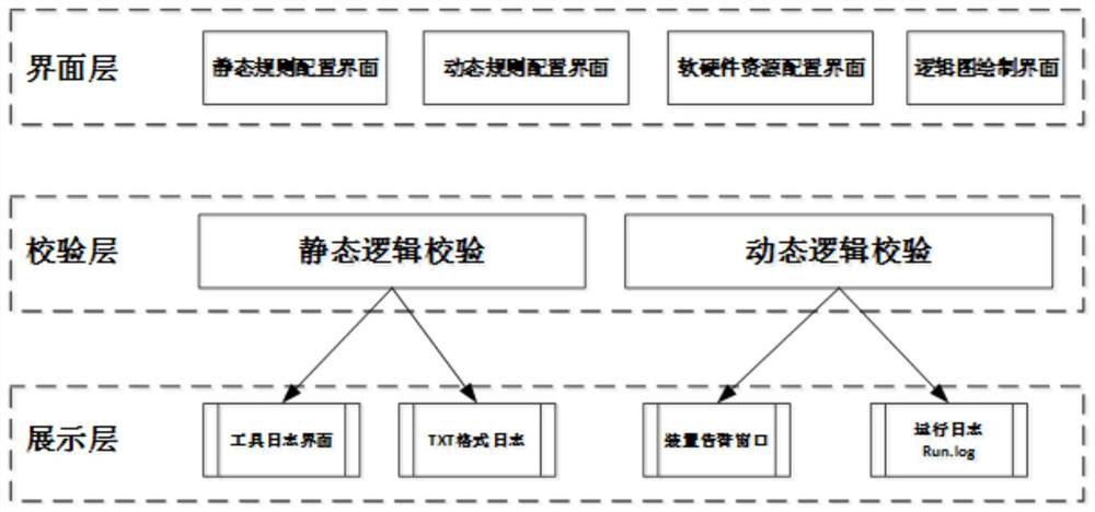
[0074] When used, a verification device for software and hardware configuration and logic diagram of a relay protection device includes the following methods:

[0075] 1) Compile the code of the verification device into an executable file NPSCheck.exe in EXE format on the Windows platform.

[0076] 2) Compile the code of the verification device into an executable dynamic verification program on the linux platform.

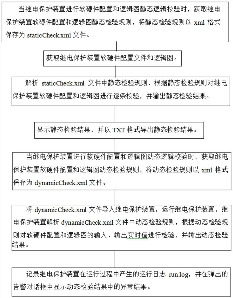
[0077] 3) Double-click to start and run NPSCheck.exe on the Windows platform, and load the software and hardware configuration and logic diagram of the relay protection device. Load staticCheck.xml, analyze the static inspection rules in the staticCheck.xml file, check the software and hardware configuration and logic diagram of the relay protection device one by one according to the static inspection rules, and output the static inspection results.

[0078] 4) Output the static verification result to the tool log interface of NPSCheck.exe, and export the log in t...


PUM


Abstract

The invention discloses a verification method and device for software and hardware configuration and a logic diagram of a relay protection device, different static verification rules and dynamic verification rules are configured for the software and hardware configuration and the logic diagram respectively, and the rules are stored as files in an XML format; the static verification rule and the dynamic verification rule are analyzed into code logic, and corresponding verification is conducted in the development stage and the operation stage; a static detection result is displayed on a development tool in the development stage, and a dynamic detection result is displayed in a device running log. According to the relay protection device software and hardware configuration and logic diagram verification method and device, the verification result can be flexibly configured and visually displayed, and static verification and dynamic verification are supported at the same time.

Description

technical field [0001] The invention relates to a method and device for verifying software and hardware configurations and logic diagrams of a relay protection device, belonging to the technical field of relay protection. Background technique [0002] The software and hardware configuration and logic diagram of current relay protection devices are very complex and abstract. Traditional software and hardware configuration and logic diagram verification methods have the following disadvantages: [0003] (1) The traditional software and hardware configuration and logic diagram checking and verification methods are solidified in the code, which is poor in flexibility, customization and maintainability. [0004] (2) The traditional software and hardware configuration and logic diagram inspection and verification methods can only be verified dynamically, that is, the verification can only be performed during the device operation stage; static verification cannot be performed, tha...

Claims


Application Information

Patent Timeline
Patent Type & Authority Applications(China)
IPC IPC(8): G06F11/36
CPCG06F11/3608
Inventor 薛钟习伟董贝李肖博张尧姚浩白晋川王浩
Owner GUODIAN NANJING AUTOMATION
Learn More