Photovoltaic power generation panel capable of being automatically unfolded and folded
A photovoltaic power generation panel and automatic deployment technology, applied in the direction of photovoltaic power generation, photovoltaic module, photovoltaic module support structure, etc., can solve the problem of inconvenient photovoltaic power generation panel angle adjustment, mutual shielding of photovoltaic power generation panels, unable to ensure normal operation of photovoltaic power generation panels, etc. question
- Summary
- Abstract
- Description
- Claims
- Application Information
AI Technical Summary
Problems solved by technology
Method used
Image
Examples
Embodiment 1
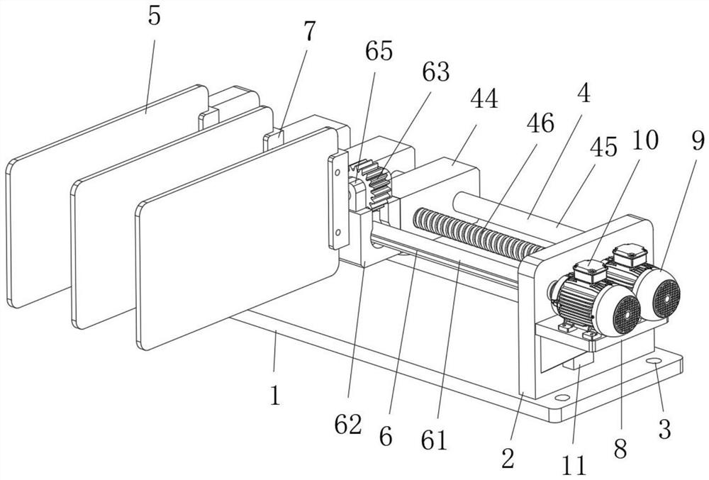
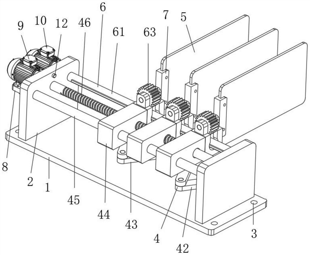
[0026] Embodiment 1: A photovoltaic power generation panel that can be automatically unfolded and folded, including an installation base plate 1, a folding and shrinking mechanism 4 and an angle adjustment mechanism 6;
[0027] Installation base plate 1: The installation base plate 1 provides an installation place for other components, and its upper surface is provided with two symmetrically distributed installation uprights 2, the installation uprights 2 are convenient for the installation of other components, and also include installation holes 3, which are convenient The device is fixed at the installation position, and the installation holes 3 are respectively opened at the four corners of the upper surface of the installation base plate;
[0028] Folding and shrinking mechanism 4: the folding and shrinking mechanism 4 can drive other components to be folded and shrunk, and is arranged between two installation vertical plates 2;
[0029] Angle adjustment mechanism 6: the a...
Embodiment 2
[0035] The difference between this embodiment and Embodiment 1 is:
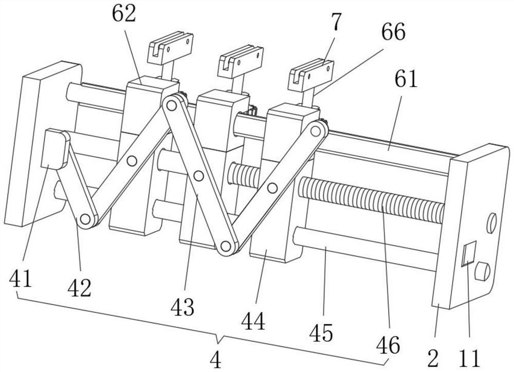
[0036]In this embodiment, the folding and retracting mechanism 4 includes a mounting block 41, a swing arm 42, a linkage arm 43, a shrinking square seat 44, a guide rod 45 and a stud 46, and the guide rod 45 is arranged at the rear end between the two installation risers 2 , the stud 46 is rotatably connected to the middle part between the two installation vertical plates 2 through bearings, and the contraction square seat 44 is all slidably connected to the outside of the guide rod 45, and the threaded hole provided at the front end of the contraction square seat 44 on the far right is connected to the threaded hole of the stud 46 Threaded connection, the studs 46 pass through the round holes provided at the front ends of the remaining shrinking square seats 44 successively, and the linkage arms 43 are connected to the front side of the lower surface of the shrinking square seat 44 through rotating shafts res...
Embodiment 3
[0039] The difference between this embodiment and Embodiment 1 is:
[0040] In this embodiment, the angle adjustment mechanism 6 includes a spline shaft rod 61, a mounting seat 62 and an outer scroll sleeve rod 64. The spline shaft rod 61 is rotatably connected to the front side between the two mounting vertical plates 2 through a bearing, and the mounting seat 62 are respectively arranged at the front end of the shrinking square seat 44, and the outer scroll sleeve rods 64 are respectively connected to the inside of the mounting seat 62 through bearings, and the inline sliding openings opened in the middle of the outer scroll sleeve rods 64 are connected with the spline shaft rod 61 Slidingly connected, the angle adjustment mechanism 6 also includes a turbine 63, a fixed seat 65 and a rotating arm 66, and the fixed seat 65 is respectively arranged on the front and rear sides of the upper surface of the mounting seat 62, between two fixed seats 65 on the same mounting seat 62 ...
PUM
 Abstract
Description
Claims
Application Information
 - R&D
- Intellectual Property
- Life Sciences
- Materials
- Tech Scout
- Unparalleled Data Quality
- Higher Quality Content
- 60% Fewer Hallucinations
Browse by: Latest US Patents, China's latest patents, Technical Efficacy Thesaurus, Application Domain, Technology Topic, Popular Technical Reports.
© 2025 PatSnap. All rights reserved.Legal|Privacy policy|Modern Slavery Act Transparency Statement|Sitemap|About US| Contact US: help@patsnap.com


