
Plate drying production line

A production line and plate technology, applied in the field of plate drying production line, can solve the problems of heat loss, high energy consumption of equipment, and low space utilization

Active Publication Date: 2022-04-15
FOSHAN NANHAI XINGYUAN MACHINERY MFG
View PDF4 Cites 0 Cited by
  • Summary
  • Abstract
  • Description
  • Claims
  • Application Information

AI Technical Summary

Problems solved by technology

The heat loss caused by the inlet and outlet at both ends of the oven equipment is serious. In order to maintain the oven temperature and drying effect, the equipment consumes a lot of energy
Moreover, the material is conveyed in one direction in the oven, and the drying time is limited by the conveying speed and the length of the equipment. In order to meet the demand for a longer drying time, it is often necessary to set up a very long oven, which occupies a large space and has low space utilization. , will also lead to the problem of high energy consumption

Method used


Image

  • Plate drying production line
  • Plate drying production line
  • Plate drying production line

Examples


Embodiment Construction

[0044] This part will describe the specific embodiment of the present invention in detail, and the preferred embodiment of the present invention is shown in the accompanying drawings. Each technical feature and overall technical solution of the invention, but it should not be understood as a limitation on the protection scope of the present invention.

[0045] In the description of the present invention, it should be understood that the orientation descriptions, such as up, down, front, back, left, right, etc. indicated orientations or positional relationships are based on the orientations or positional relationships shown in the drawings, and are only In order to facilitate the description of the present invention and simplify the description, it does not indicate or imply that the device or element referred to must have a specific orientation, be constructed and operated in a specific orientation, and thus should not be construed as limiting the present invention.

[0046] I...


PUM


Abstract

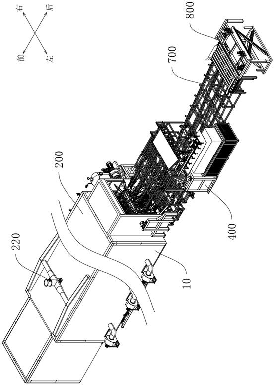
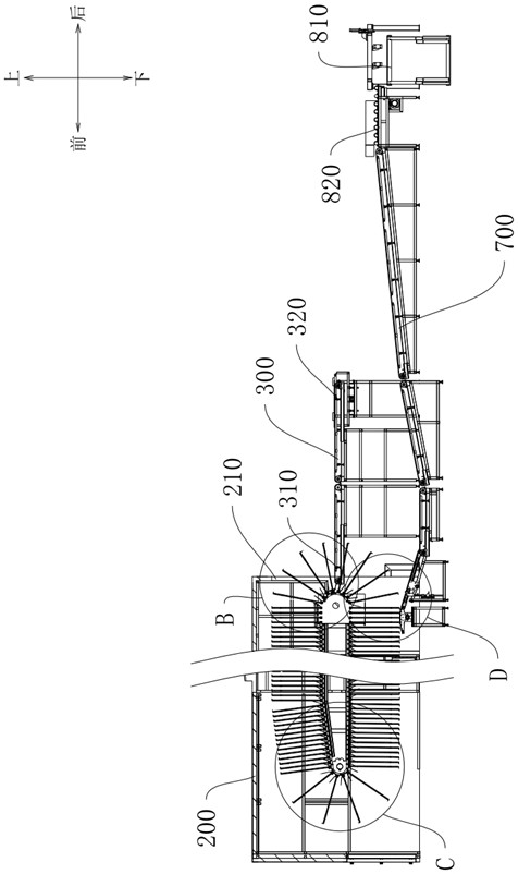
The invention relates to the technical field of production equipment, and discloses a plate drying production line. The plate drying production line comprises a circulating dryer, a plate feeding device and a plate discharging device. The circulating dryer comprises a circulating conveying device and a drying oven device arranged on the periphery of the circulating conveying device in a surrounding mode. The circulating conveying device comprises a conveying driving component and a belt plate component used for bearing external materials. The multiple band plate components are arranged and distributed along the closed-loop circulation track, and the conveying driving component is used for driving the band plate components to move along the circulation track. The plate feeding device is used for conveying external materials to the circulating conveying device, and the plate discharging device is used for conveying the materials on the circulating conveying device to the outside of the circulating dryer. According to the plate drying production line, the plates are circularly conveyed in the drying oven device and can enter and exit from the same side of the drying oven device, the space utilization rate is high, heat loss is small, and energy consumption can be effectively reduced. The method can be applied to plate processing and production.

Description

technical field [0001] The invention relates to the technical field of production equipment, in particular to a plate drying production line. Background technique [0002] In the production process of boards, especially composite boards, drying treatment is often required. In the prior art board drying production, the board is conveyed in the oven through the conveying device, the board enters from one end of the oven and is sent out from the other end, and is dried by the high-temperature hot air in the oven during the conveying process. The heat loss caused by the inlet and outlet at both ends of the oven equipment is serious. In order to maintain the oven temperature and drying effect, the energy consumption of the equipment is relatively high. Moreover, the material is conveyed in one direction in the oven, and the drying time is limited by the conveying speed and the length of the equipment. In order to meet the demand for a longer drying time, it is often necessary to...

Claims


Application Information

Patent Timeline
IPC IPC(8): F26B15/12F26B25/00F26B25/02
CPCF26B15/12F26B25/003F26B25/02Y02P70/10
Inventor 袁文成王冬琴袁红超
Owner FOSHAN NANHAI XINGYUAN MACHINERY MFG
Learn More