
Low-speed large-torque permanent magnet motor all-in-one machine

A low-speed, high-torque, permanent magnet motor technology, applied in electromechanical devices, electrical components, electric components, etc., can solve the problems of limited site conditions, high tonnage, and reduced service life, and achieves improved installation efficiency, increased service life, and high efficiency. The effect of power factor

Pending Publication Date: 2022-04-12
HUAINAN WANTAI ELECTRONICS
View PDF0 Cites 0 Cited by
  • Summary
  • Abstract
  • Description
  • Claims
  • Application Information

AI Technical Summary

Problems solved by technology

[0002] At present, removing mechanical devices such as hydraulic couplings and multi-stage pulleys, and adopting low-speed permanent magnet direct drive systems can give full play to the advantages of low-speed permanent magnet synchronous motors; however, in many cases, due to the size of permanent magnet direct drive motors Due to large size, high tonnage, and limited site conditions, the old low-speed permanent magnet motor cannot be installed and used normally.
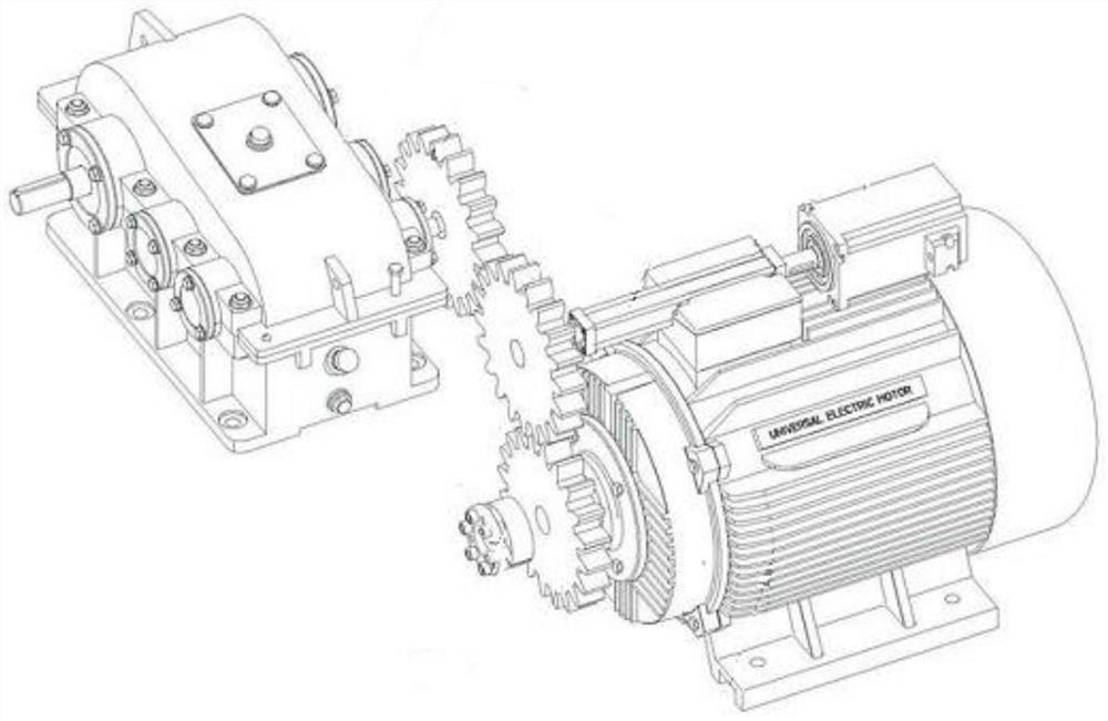
[0003] like figure 1 In the prior art shown, after the traditional low-speed high-torque permanent magnet motor has been used for a long time, there will be a small amount of dust on the output shaft of the permanent magnet motor, which will easily affect its operation, and it is inconvenient to disassemble it and the reducer for maintenance. At the same time, due to the influence of the humid environment around electrical components such as permanent magnet motors and reducers, it is easy to reduce the service life of electrical components such as permanent magnet motors and reducers

Method used


Image

  • Low-speed large-torque permanent magnet motor all-in-one machine
  • Low-speed large-torque permanent magnet motor all-in-one machine
  • Low-speed large-torque permanent magnet motor all-in-one machine

Examples


Embodiment Construction

[0029] The technical solutions of the present invention will be clearly and completely described below in conjunction with the embodiments. Apparently, the described embodiments are only some of the embodiments of the present invention, not all of them. Based on the embodiments of the present invention, all other embodiments obtained by persons of ordinary skill in the art without creative efforts fall within the protection scope of the present invention.

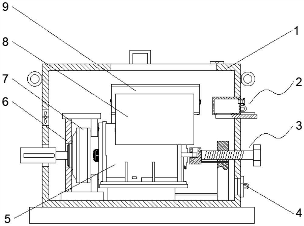
[0030] see figure 2 As shown, the low-speed and high-torque permanent magnet motor integrated machine includes a casing 1, a permanent magnet motor 5 is arranged inside the cavity of the casing 1, and a fixing frame 6 fixedly connected to the inner wall of the casing 1 is arranged on one side of the permanent magnet motor 5 to fix the A reducer 7 is fixedly installed in the middle of the frame 6, the output end of the reducer 7 moves through the casing 1, the permanent magnet motor 5 is coupled with the inner spline of the...


PUM


Abstract

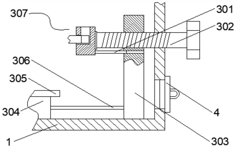
The invention relates to a low-speed large-torque permanent magnet motor all-in-one machine which comprises a shell, a permanent magnet motor is arranged in the shell, a push-pull mechanism is arranged on one side of the permanent magnet motor and comprises a limiting plate fixedly connected with the shell, and a threaded rod is arranged on one side of the limiting plate. One end of the threaded rod is in threaded connection with the limiting plate and the shell and is fixedly provided with a rotating head, the other end of the threaded rod is provided with a clamping mechanism, the clamping mechanism comprises a clamping base rotationally connected with the threaded rod, a clamping groove is formed in the top face of the clamping base, and a groove is formed in the side face, facing the permanent magnet motor, of the clamping base; a clamping block is fixedly installed at the position, corresponding to the groove, of the permanent magnet motor, the clamping mechanism is pulled to move through rotation of the threaded rod, the permanent magnet motor is moved to the set position, the opening and closing door is opened, and therefore the permanent magnet motor can be conveniently taken out for maintenance.

Description

technical field [0001] The invention relates to the technical field of permanent magnet motors, in particular to a low-speed and high-torque permanent magnet motor integrated machine. Background technique [0002] At present, removing mechanical devices such as hydraulic couplings and multi-stage pulleys, and adopting low-speed permanent magnet direct drive systems can give full play to the advantages of low-speed permanent magnet synchronous motors; however, in many cases, due to the size of permanent magnet direct drive motors Because of large size, high tonnage, and limited site conditions, the old low-speed permanent magnet motor cannot be installed and used normally. [0003] Such as figure 1 In the prior art shown, after the traditional low-speed high-torque permanent magnet motor has been used for a long time, there will be a small amount of dust on the output shaft of the permanent magnet motor, which will easily affect its operation, and it is inconvenient to disas...

Claims


Application Information

Patent Timeline
Patent Type & Authority Applications(China)
IPC IPC(8): H02K5/26H02K5/20H02K5/10H02K11/33H02K7/10B01D53/28
Inventor 吴兴刚张悦生田建波张冬杰秦忠根王玉龙田华明邱铭庄郭德道
Owner HUAINAN WANTAI ELECTRONICS
Learn More