Vibration liquid level sensor

A liquid level sensor, No. 1 technology, applied in the field of sensors, can solve problems such as affecting the rise of the magnetic floating ball, and achieve the effect of avoiding waste and preventing corrosion

Pending Publication Date: 2022-04-12
徐玲玲
View PDF1 Cites 1 Cited by
  • Summary
  • Abstract
  • Description
  • Claims
  • Application Information

AI Technical Summary

Problems solved by technology

[0005] The purpose of the present invention is to provide a vibrating liquid level sensor, which mainly solves the problem. Problem with the ascent of the ball

Method used


Image

  • Vibration liquid level sensor
  • Vibration liquid level sensor
  • Vibration liquid level sensor

Examples


Embodiment approach

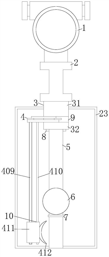
[0052] As an embodiment of the present invention, the No. 1 power unit 401 and the No. 2 power unit 12 are both motors.

[0053] During the use of the vibrating liquid level sensor, by setting the No. 1 power unit 401 and No. 2 power unit 12 as motors, they can be driven with a small amount of energy and can be precisely controlled to avoid energy waste.

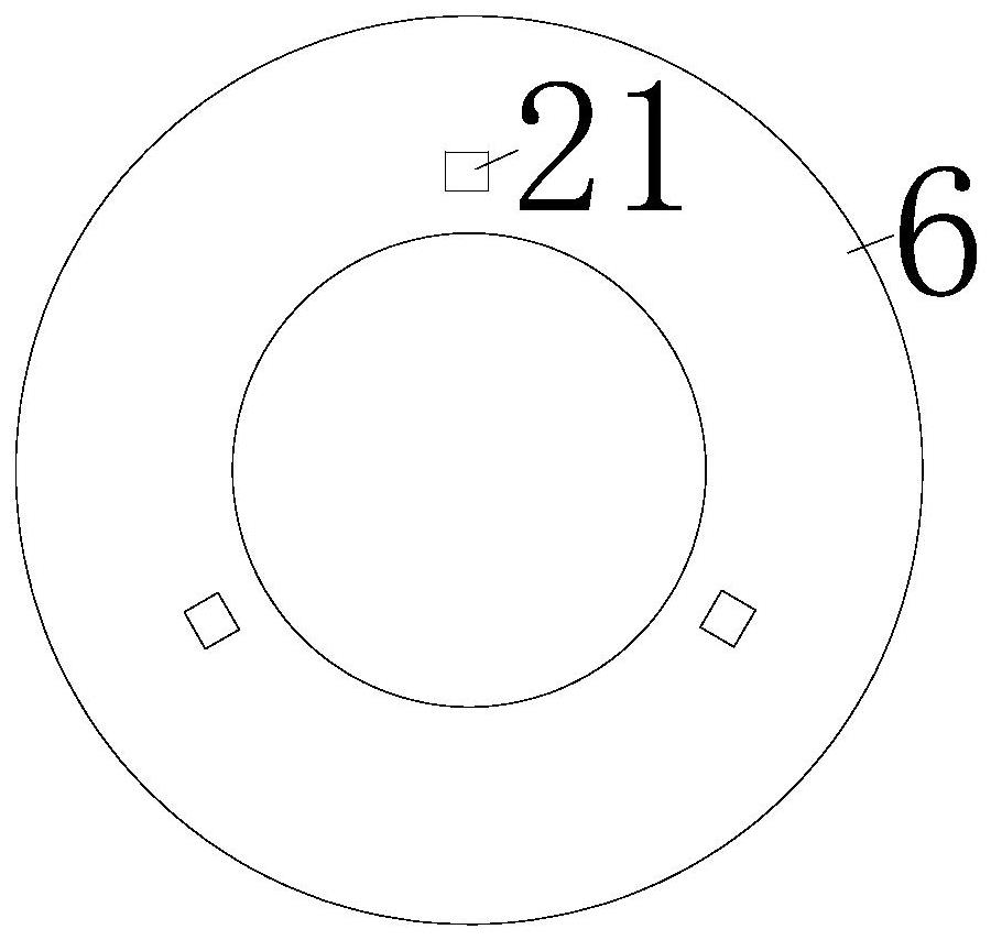
[0054] Working principle: when the present invention is installed, by setting the installation flange 2, the installation flange 2 is installed at the installation place, and the measuring rod 5 is submerged in the water to be measured. At this time, the magnetic floating ball 6 sinks and floats in the water, so that The magnetic induction electronic component 17 on the upper end of the electronic component circuit board 16 on the same horizontal line as the magnetic float 6 senses the magnetic induction line, and then different liquid level signals can be transmitted to different water levels, and the liquid level informatio...


PUM


Abstract

The invention relates to the technical field of sensors, in particular to a vibration liquid level sensor which comprises a liquid level sensor body, the lower end of the liquid level sensor body is fixedly connected with a mounting flange, the lower end of the mounting flange is fixedly connected with a protective shell, the protective shell is divided into an upper shell and a lower shell, a rotating groove is formed between the upper shell and the lower shell, and the rotating groove is fixedly connected with the mounting flange. A cleaning unit is arranged in the lower shell, a measuring rod is fixedly connected to the lower end of the cleaning unit, a magnetic floating ball is slidably connected to the outer surface of the measuring rod, and the problems that after a liquid level sensor in the market is soaked in liquid for a period of time, water stains are likely to be attached to the surface, and automatic cleaning is difficult to achieve are solved.

Description

technical field [0001] The invention relates to the technical field of sensors, in particular to a vibration liquid level sensor. Background technique [0002] A liquid level sensor is a pressure sensor that measures liquid level. The static pressure input liquid level transmitter is based on the principle that the measured liquid static pressure is proportional to the height of the liquid, and uses foreign advanced isolated diffused silicon sensitive elements or ceramic capacitor pressure sensitive sensors to convert static pressure into electrical signals , and then converted into a standard electrical signal after temperature compensation and linearity correction. [0003] The patent number is: 201910125251.5 discloses a liquid level sensor, including a liquid level sensor body and a connecting flange, the bottom end of the liquid level sensor body is fixedly connected with a connecting flange, and the bottom end of the connecting flange is fixedly connected with a a fi...

Claims


Application Information

Patent Timeline
Patent Type & Authority Applications(China)
IPC IPC(8): G01F23/72B08B1/00B08B13/00
Inventor 徐玲玲张运超
Owner 徐玲玲
Why Eureka
Try Eureka