Magnetofluid damping joint for camera support of inspection robot

A technology for inspection robots and cameras, applied in machine/stand, supporting machine, spring/shock absorber, etc., can solve the problems of unstable shock absorption performance, small damping of spring shock absorber, poor environmental adaptability, etc. Responsive, responsive, and reliable effects

Active Publication Date: 2022-04-12
姜堰经济开发区科创中心
View PDF7 Cites 0 Cited by
  • Summary
  • Abstract
  • Description
  • Claims
  • Application Information

AI Technical Summary

Problems solved by technology

The spring shock absorber has small damping and unstable shock absorption performance; the rubber shock absorber can only adapt to a specific situation and has poor environmental adaptability

Method used


Image

  • Magnetofluid damping joint for camera support of inspection robot
  • Magnetofluid damping joint for camera support of inspection robot
  • Magnetofluid damping joint for camera support of inspection robot

Examples


Embodiment Construction

[0020] The present invention is described in further detail now in conjunction with accompanying drawing. These drawings are all simplified schematic diagrams, which only illustrate the basic structure of the present invention in a schematic manner, so they only show the configurations related to the present invention.

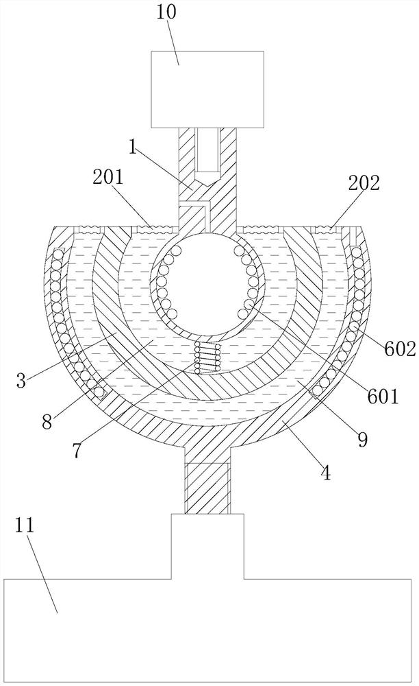
[0021] Such as Figure 1 ~ Figure 3 A ferrofluid shock-absorbing joint used for inspection robot camera bracket shown, including upper limb 1, middle joint 3 and lower limb 4,

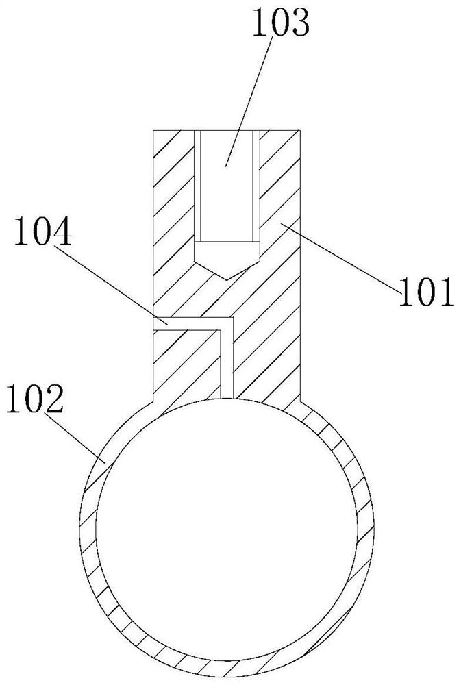
[0022] The upper limb 1: consists of an upper cylinder 101 and a lower sphere 102, the end of the upper cylinder 101 is provided with a threaded hole 103 for connecting the camera 10, the outer cylindrical surface of the joint between the upper cylinder 101 and the lower sphere 102 The upper part is provided with external threads; the lower sphere 102 is a spherical shell with a hollow interior, and an upper coil 601 is wound on the inner wall of the lower sphere 102 .
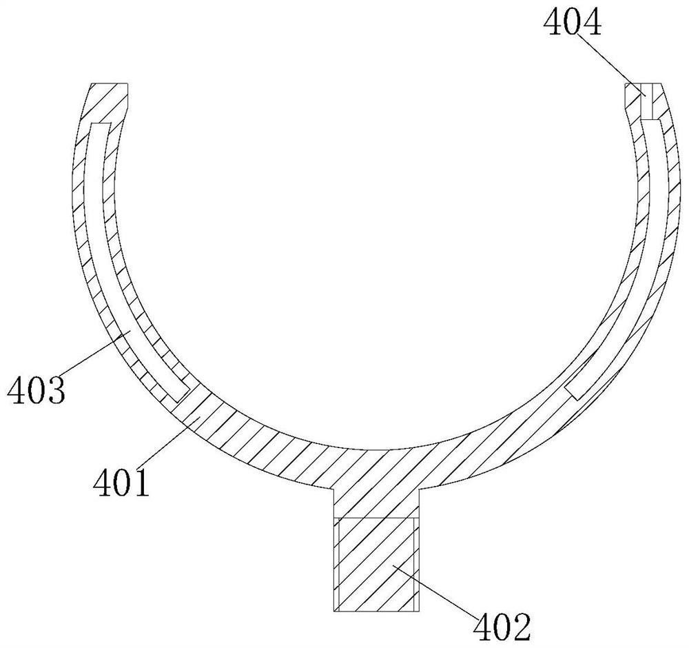
[0023] The l...


PUM


Abstract

The magnetofluid damping joint comprises an upper limb, a lower limb and a bowl-shaped middle joint, the upper limb comprises an upper cylinder and a lower sphere, a camera is installed at the top end of the upper cylinder, the lower sphere is located in the middle joint, an upper coil is arranged in an inner cavity of the lower sphere, and a lower coil is arranged in an inner cavity of the lower sphere. The bottom of the lower ball body is flexibly connected with the inner bottom wall of the middle joint through a spring, and an inner magnetorheological cavity filled with magnetorheological fluid is formed between the inner wall of the middle joint and the periphery of the lower ball body; the lower limb comprises an upper shell and a lower column body, the middle joint is located in the upper shell, an outer magnetorheological cavity filled with magnetorheological fluid is formed between the middle joint and the inner wall of the upper shell, the middle joint can rotate or be instantly fixed in the inner magnetorheological cavity and the outer magnetorheological cavity, an annular cavity is formed in the upper shell, a lower coil is arranged in the annular cavity, and the lower coil is connected with the lower column body. And the lower column body is mounted on the inspection robot main body.

Description

technical field [0001] The invention relates to the technical field of shock absorption for robots, in particular to a magnetic fluid shock absorption joint for a camera bracket of an inspection robot. Background technique [0002] The inspection robot uses a mobile robot as the carrier, and a camera, infrared thermal imager and other detection instruments as the load system. The device used to carry the camera is a pan-tilt, which can be lifted and lowered in a large range during the inspection process. At present, the inspection robot used in underground coal mines is different from the daily indoor and outdoor inspection robot. During the underground work, it will encounter harsh ground conditions, causing large vibrations in the main body of the inspection robot, which is then transmitted to the cloud platform The camera on the camera greatly affects the clarity of the image captured by the camera. Therefore, the changeable underground road conditions put forward higher...

Claims


Application Information

Patent Timeline
IPC IPC(8): F16F15/067F16F15/16F16F15/18F16M11/14F16M13/02B25J17/02B25J19/00
Inventor 谷秋梅刘新华
Owner 姜堰经济开发区科创中心
Why Eureka
Try Eureka